Time to read: 6 min
4-Axis CNC Machining: Capabilities, Applications, and Design Guidelines
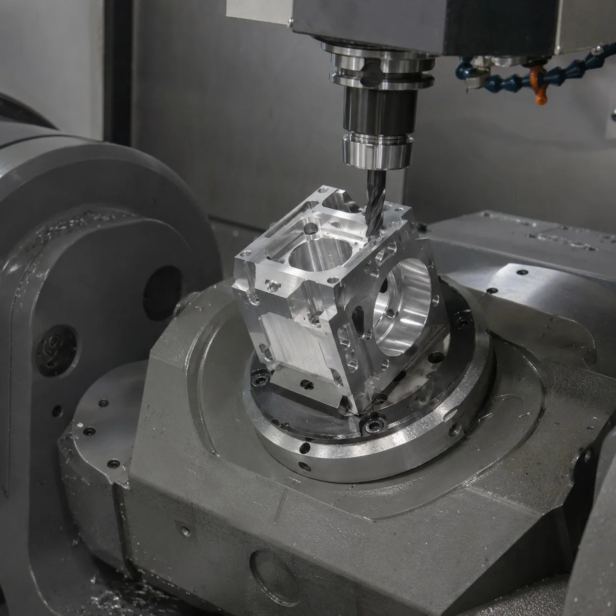
Four-axis CNC machining adds controlled rotation to the familiar X, Y, and Z movements of a three-axis machining center. This extra axis allows a part to be indexed or machined around a cylindrical surface without repeated manual repositioning. For the right geometry, 4-axis machining can reduce setups, improve feature alignment, and shorten lead time.
It is not automatically better than 3-axis or 5-axis machining. The value depends on part shape, feature locations, tolerance relationships, and production volume. This guide explains how 4-axis CNC machining works, where it is most useful, and how to design parts that take advantage of the process.
How 4-Axis CNC Machining Works
A standard 3-axis mill moves the cutting tool along X, Y, and Z. A 4-axis machine adds rotation, usually around the X-axis. This rotary axis is commonly called the A-axis. The workpiece is mounted in a rotary fixture, chuck, or trunnion so different sides can be presented to the cutting tool.
There are two common operating methods. In indexed 4-axis machining, the part rotates to a fixed angle, stops, and is then machined using normal three-axis toolpaths. In simultaneous 4-axis machining, the rotary axis moves while cutting takes place. Simultaneous motion can create wrapped features, helical paths, and smooth contours around cylindrical parts, but it requires more advanced programming.
When 4-Axis Machining Reduces Setups
Many prismatic parts require machining on four sides. On a 3-axis machine, the operator may need to stop, unclamp, rotate, realign, and re-probe the part for each side. Every setup introduces time and the possibility of positional error. With a rotary axis, several faces can be machined in one clamping.
This is valuable for housings with side holes, blocks with repeated radial features, valve bodies, brackets with angled interfaces, and components that require consistent relationships between several faces. The process can also improve repeatability in low-volume production because fewer manual operations are required.
Typical Applications
- Cylindrical housings with ports or holes around the circumference.
- Shafts with flats, slots, keyways, or cross holes.
- Robotic joint bodies and actuator components.
- Medical and optical housings with multiple indexed features.
- Impellers, cam-like parts, and helical details when geometry allows.
- Aerospace brackets with features on several sides.
- Fixture components and tooling blocks with repeated angular patterns.
Four-axis machining is also useful for engraving or milling text around a cylindrical surface. However, deep undercuts and features that require the tool to approach from many unrelated angles may still require 5-axis machining.
4-Axis vs. 3-Axis and 5-Axis Machining
Three-axis machining remains efficient for flat plates, simple pockets, and parts with features concentrated on one or two sides. It is usually easier to program and may have lower hourly cost. Four-axis machining becomes attractive when the part needs rotation around one primary axis.
Five-axis machining adds another rotary direction, giving the tool access to more complex angles. It is better for sculpted surfaces, impellers, complex aerospace components, and parts with multiple angled interfaces. The additional flexibility comes with higher programming and machine cost. Choosing 4-axis instead of 5-axis can be economical when all critical features can be reached with one rotary axis.
Design Guidelines for 4-Axis CNC Parts
Align Features Around a Common Axis
The process is most efficient when side features are organized around the rotary centerline. Repeated hole patterns, flats, grooves, or ports at 90-degree or regular angular intervals are good candidates. If each feature requires a completely different tool direction, the advantage of the fourth axis may be limited.
Provide Tool Access and Clearance
Fixtures, chucks, and tailstocks occupy space around the part. Long tools may be needed to reach deep features, but excessive reach increases vibration. Designers should avoid walls or shoulders that block the cutter. Internal corner radii should match practical tool diameters.
Control Long, Slender Parts
Long shafts and tubes may deflect during cutting. A tailstock, steady rest, or custom support can improve stability, but these devices may restrict access. The drawing should identify where support marks are acceptable and which surfaces must remain cosmetic.
Use Realistic Tolerances
One-clamping machining can improve relationships between features, but tolerance still depends on material, part stiffness, tool reach, and temperature. Apply tight position, concentricity, or runout requirements only to functional interfaces. Over-tolerancing all surfaces increases inspection time without improving performance.
Consider the Raw Material Shape
Round stock is natural for cylindrical parts, while square or rectangular stock may be better for indexed blocks. Large amounts of material removal increase time and distortion risk. Near-net blanks, extrusions, or pre-machined stock may be worth considering for repeat production.
Fixtures and Workholding
Workholding is central to 4-axis success. The part may be held in a chuck, collet, vise mounted on a rotary table, custom fixture, or between centers. The fixture must resist cutting forces while keeping the rotary center accurate. It also needs enough clearance for the tool and chips.
For repeat orders, a dedicated fixture can shorten setup time and improve consistency. For prototypes, modular fixtures may provide more flexibility. The choice should reflect quantity, geometry, tolerance, and whether the same part family will be manufactured again.
Inspection Planning
Features around a cylindrical part may be difficult to inspect with simple calipers. A CMM, rotary inspection setup, height gauge, thread gauges, or custom checking fixture may be required. The drawing should state angular position, datum references, and whether true position or profile controls the feature.
Inspection planning should be discussed before manufacturing, especially for tight angular relationships. If a requirement cannot be measured efficiently, it may create cost or disagreement even when the part functions correctly.
Preparing a 4-Axis CNC RFQ
Provide a STEP model and a dimensioned drawing. Mark the rotary centerline, critical datums, angular features, material, finish, quantity, and inspection needs. Explain which features assemble with bearings, seals, motors, or other components. This helps the manufacturing team decide whether 4-axis indexing, simultaneous machining, or another process is most appropriate.
RapidMfgPro can review multi-side CNC parts and compare 3-axis, 4-axis, and 5-axis routes. A process selected around the actual geometry can reduce setups while preserving the tolerance relationships that matter to the assembly.
Need Help Reviewing a Custom Part?
Share your CAD file and requirements to request supplier matching. Supplier capability and commercial terms must be verified before order placement.
Request Supplier Match