Time to read: 8 min
How Can You Reduce CNC Machining Costs Through Better Part Design?
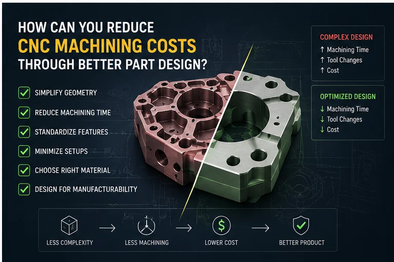
CNC machining cost is not determined only by the size of a part or the number of features in the CAD model. Two components with similar dimensions can have very different prices because one can be machined from standard stock in two stable setups, while the other requires a large material block, long-reach cutters, five-axis access, tight tolerances, manual deburring, multiple inspections, and an expensive surface finish.
Better part design reduces cost by removing manufacturing difficulty that does not contribute to product function. This does not mean making every component simple, loose, or low quality. It means applying precision only where it creates value, selecting geometry that matches available tools, and designing the machining, finishing, inspection, and assembly route as one coordinated process.
The most useful cost-reduction question is not:
How can the supplier machine this design more cheaply?
It is:
Which features, tolerances, materials, finishes, and documentation requirements are creating cost, and which of them are truly necessary for function?
This guide explains where CNC costs originate and how better design can reduce material waste, machine time, setups, tooling, inspection, finishing, and rejection risk. It also explains when a lower-cost design change can damage performance and how RapidMFGPro approaches design review and supplier matching for cost-sensitive CNC projects.
Where Does the Cost of a CNC-Machined Part Come From?
Designers can reduce machining cost more effectively when they understand how a supplier builds a quotation. The final price usually combines several cost categories rather than one hourly machine rate.
Material and Stock Preparation
Material cost includes more than the final weight of the component. It may include:
- The purchased bar, plate, tube, forging, or block
- Cutting and stock-preparation labor
- Minimum purchase quantities
- Material certification
- Yield loss and offcuts
- Extra stock for workholding and cleanup
A lightweight finished part can still be expensive if it must be cut from a much larger solid block and most of the purchased material becomes chips.
Programming, Setup, and Machine Time
Programming and setup include:
- CAM programming
- Fixture selection or design
- Tool preparation
- Work offset and probing
- First-piece adjustment
- Part repositioning
Machine time includes roughing, finishing, drilling, tapping, tool changes, probing, and noncutting movement. A part that requires four orientations can cost more than a larger part completed in one or two setups.
Tooling, Inspection, Finishing, and Risk
Additional cost can come from:
- Special cutters and long-reach tools
- Tool wear in difficult materials
- CMM programming and inspection reports
- Grinding, lapping, polishing, or EDM
- Anodizing, plating, heat treatment, or coating
- Clean packaging and traceability
- Expected scrap or rework risk
A supplier may price a high-risk feature above its direct cutting time because one tool failure or finishing defect can scrap a nearly completed part.
| Cost category | Design conditions that increase it | Common design response |
|---|---|---|
| Raw material | Large envelope, rare alloy, heavy stock removal | Use standard stock, near-net shape, or a more efficient orientation |
| Programming | Freeform surfaces, many unique features, unclear drawings | Simplify geometry and provide consistent product definition |
| Setup | Features on many faces or difficult clamping | Group features into fewer machining directions |
| Machine time | Deep pockets, small tools, heavy removal, fine finishes | Increase radii, reduce depth, and remove unnecessary finishing |
| Tooling | Special threads, undercuts, tiny radii, long overhangs | Use standard tools and accessible features |
| Inspection | Tight tolerances on many features, full reports | Control only functional features and define sampling intelligently |
| Secondary operations | Multiple finishes, polishing, masking, manual deburring | Eliminate or localize secondary requirements |
| Risk allowance | Thin walls, difficult alloys, late-stage high-risk features | Improve stiffness, process sequence, and prototype validation |
Reduce Cost by Choosing the Right Manufacturing Process First
A component may be machinable by several methods, but one route can be much more efficient than another. Design should begin by identifying the natural process family.
Design Rotational Parts for CNC Turning
A part dominated by concentric diameters, grooves, axial holes, tapers, and threads is usually economical on a lathe or turning center.
Turning becomes less efficient when the design contains:
- Large off-axis pockets
- Many radial features
- Square flanges
- Deep milled flats
- Features requiring several indexed orientations
Live tooling and mill-turn machines can combine operations, but the designer should not assume every turned supplier has the same multi-axis capability.
Design Prismatic Parts for Milling
Parts dominated by flat faces, pockets, bosses, and hole patterns are natural milling components. Costs rise when milling must reproduce geometry that could have been created from extrusion, tubing, sheet, or turned stock.
Consider Near-Net-Shape Starting Material
Potential starting forms include:
- Extrusions
- Tube
- Hollow bar
- Forgings
- Castings
- Laser-cut blanks
- Waterjet-cut blanks
Near-net stock can reduce chips and cycle time, especially at production volume. It can also introduce tooling, minimum-order, dimensional, surface, and qualification costs. The break-even point should be reviewed rather than assuming a custom blank is always cheaper.
Match the Part Envelope to Standard Stock
A few millimetres added to a part can force the supplier into a larger plate, bar, or machine envelope. Stock efficiency should be considered before finalizing the outside dimensions.
Avoid Dimensions Just Above a Common Stock Size
If a component is slightly thicker than an available plate, it may require purchasing the next standard thickness and removing substantially more material.
The same issue applies to:
- Round-bar diameters
- Square-bar sizes
- Tube wall thicknesses
- Extrusion envelopes
- Machine travel limits
Reducing a nonfunctional dimension slightly can lower material cost and roughing time.
Leave Practical Workholding Stock
The supplier needs material to grip, clamp, or locate. A design that uses the full purchased envelope may require soft jaws, tabs, sacrificial features, adhesive workholding, or a larger starting block.
Design review should consider where the part can be held during:
- First-operation roughing
- Second-operation finishing
- Five-axis machining
- Grinding or inspection
Orient the Part to Reduce Waste
Changing the stock orientation can reduce purchased volume, but it may change grain direction, material properties, tool access, and setup count.
For structural aluminum, forgings, rolled plate, composites, and directional materials, stock efficiency should not override required mechanical orientation.
Reduce the Amount of Material That Must Be Removed
Machining cost generally rises with the volume of metal removed, but the relationship is affected by material, tool access, chip evacuation, and machine power.
Do Not Hollow Out Parts Without a Functional Reason
Large weight-reduction pockets may save a small amount of product mass while adding long roughing cycles. They can also create thin walls and distortion.
Hollowing may be justified for:
- Aerospace mass reduction
- Robotic payload control
- Thermal response
- Dynamic balance
- Material cost in expensive alloys
For static brackets and fixtures, leaving more material can sometimes be cheaper than machining it away.
Use Open Pockets Instead of Closed Deep Cavities
Open geometry improves:
- Tool access
- Chip evacuation
- Coolant delivery
- Use of larger cutters
- Inspection access
Sandvik notes that long and deep pockets require long overhangs and are more vulnerable to vibration. Autodesk also identifies deep pockets as features that often require specialty tooling or additional process complexity.
Consider a Fabricated or Assembled Design
A monolithic part may be split into:
- A base and cover
- A turned insert and milled body
- A plate and standard spacer
- A sheet-metal enclosure with machined interfaces
This can reduce stock removal and setup complexity. It also adds fasteners, joints, alignment features, assembly labor, and possible leakage or stiffness risks. Part splitting should be evaluated at total assembly cost, not machining cost alone.
Reduce the Number of Machining Setups
Each setup introduces labor, fixture time, datum transfer, probing, and alignment risk. Reducing orientations is one of the strongest ways to lower cost.
Group Features into Common Tool Directions
Where function allows, place holes, pockets, and slots so they can be reached from the same face.
A three-axis milled component is often cheapest when most features are accessible from:
- The top
- One flipped bottom operation
- At most one controlled side operation
Features distributed across six faces may justify five-axis machining, but not every supplier or volume level benefits equally from it.
Design Stable Datum and Clamping Surfaces
Useful workholding features include:
- Flat parallel faces
- Accessible clamping margins
- Temporary bosses or tabs
- Repeatable holes or locating pads
- Noncritical surfaces for jaw contact
Irregular outer shapes with no clamping area can require custom fixtures or sacrificial stock.
Avoid Late-Stage Features That Require Reorientation
A single angled hole, back-side counterbore, hidden slot, or cross-hole may add a complete setup. If the feature is not essential, align it with an existing machining direction or redesign the mating component.
| Design choice | Likely setup effect | Lower-cost alternative |
|---|---|---|
| Holes normal to six faces | Multiple indexing operations | Group holes into fewer faces |
| Back-side counterbore | Part flip or specialty tool | Move seat to accessible side or use different fastener |
| Angled hole | Rotary or five-axis setup | Use a normal hole and angled fitting when acceptable |
| Irregular curved exterior | Custom jaws or sacrificial stock | Add temporary locating and clamping features |
| Precision features with unrelated datums | Repeated realignment and inspection | Create a coherent datum system |
| Undercut visible only from one hidden direction | Special tool and extra setup | Open the feature or split the assembly |
Use Internal Radii That Allow Larger Cutting Tools
Sharp or very small internal corners force small tools and rest-machining operations.
Make the Part Radius Larger Than the Cutter Radius
A cutter entering a corner with a part radius equal to the tool radius experiences a large engagement increase. Autodesk machining guidance shows that forcing a tool into sharp corners leaves more difficult tool motion, while adding a cutting radius smooths the path but may require later rest machining.
A larger internal radius allows:
- A larger end mill
- Higher material-removal rate
- Lower deflection
- Better surface finish
- Longer tool life
Do Not Require Sharp Corners Unless They Are Functional
A sharp blind internal corner may require sinker EDM, broaching, or manual finishing. If a square item must fit, consider:
- Chamfering the mating item
- Adding dog-bone reliefs
- Using a separate insert
- Opening the corner geometry
Standardize Corner Radii
Using one or two practical radius families across the part can reduce tool changes and simplify programming. Avoid several nearly identical values unless they control different mating conditions.
Avoid Deep and Narrow Pockets
Deep pockets require long cutters and can create vibration, chip recutting, and poor coolant access.
Increase Pocket Width or Corner Radius
A wider pocket can accept a larger, stiffer cutter. If the opening is narrow but the cavity becomes wide underneath, tool-holder clearance may still control the process.
Reduce Depth When the Full Volume Is Not Functional
Consider whether the pocket requires:
- Full depth everywhere
- A flat bottom
- Vertical walls to the bottom
- The same tolerance at every depth
A stepped cavity, relief, or local functional land may be cheaper.
Provide Chip and Coolant Escape
Closed cavities can recut chips and damage surface finish. Sandvik recommends strong chip evacuation and coolant control for cavity operations. Design changes such as open sides, drain paths, or larger clearances can improve the process.
Keep Walls and Floors Thick Enough to Remain Stable
Thin features deflect under cutting force and may distort after material removal or heat treatment.
Thin Walls Require Slower, Staged Machining
A thin wall may need:
- Balanced material removal
- Multiple finishing passes
- Special support fixtures
- Low cutting force
- Inspection after unclamping
Autodesk manufacturing guidance notes that machining one side of a thin wall completely before the other can cause wall failure, illustrating why process sequencing becomes more complex.
Avoid Large Thickness Changes
Heavy bosses connected to thin membranes can distort during machining, heat treatment, welding, or coating. Smoother thickness transitions can improve both structural behavior and process stability.
Define the Minimum Functional Thickness
Do not specify a thin wall only to reduce weight unless the mass benefit matters. A small thickness increase can improve:
- Stiffness
- Dimensional repeatability
- Surface finish
- Clamping stability
- Production yield
Simplify Holes, Threads, and Tapped Features
Holemaking is efficient when designs use standard diameters, practical depths, accessible directions, and common thread specifications.
Prefer Through Holes Over Blind Holes
Through holes improve chip evacuation and are easier to drill, tap, clean, and inspect. Blind holes require extra depth for the drill point, tap lead, and chips.
Use Standard Diameters and Threads
Standard drills, reamers, taps, and gauges reduce tooling and inspection changes. Avoid custom threads or arbitrary hole sizes unless they control a real interface.
Avoid Deep Small-Diameter Holes
Deep holes require slender tools, through-tool coolant, peck cycles, or specialized drilling. If possible:
- Increase the diameter
- Reduce depth
- Drill from both sides with an acceptable intersection
- Use tubing or a separate manifold component
Eliminate Unnecessary Undercuts and Special Features
Undercuts are features that a standard tool cannot reach directly from the main access direction.
Common High-Cost Undercuts
Examples include:
- Internal retaining-ring grooves
- Reverse counterbores
- Hidden T-slots
- Internal dovetails
- Back-side chamfers
- Re-entrant freeform geometry
Use Standard Tool Geometry
If an undercut is necessary, use a standard width, radius, depth, or thread relief that matches available tooling. Custom form cutters increase lead time and risk.
Open the Feature or Split the Part
A hidden internal feature may become simple if a wall is removed, a cover is added, or an insert is machined separately. The effect on assembly, strength, sealing, and tolerance stack must still be reviewed.
Apply Tight Tolerances Only to Functional Features
Tolerances influence process selection, number of finishing passes, inspection, climate control, and scrap risk.
Use General Tolerances for Noncritical Dimensions
ISO 2768-1:1989 remains current as of July 2026, although ISO indicates that a replacement is in development. It provides general tolerance classes for linear and angular dimensions without individual tolerance indications.
Using a coherent general tolerance system can reduce drawing clutter and prevent unnecessary tight control on cosmetic or clearance dimensions.
Use Fits and GD&T to Express Function
ISO 286-1 provides a standardized system for tolerances and fits on cylinders and parallel opposite surfaces. ASME Y14.5 establishes the design language for GD&T.
Functional controls can be more economical than uniformly tight coordinate tolerances. Examples include:
- Position for a bolt-hole pattern
- Profile for a freeform surface
- Perpendicularity for a bearing axis
- Flatness only on a sealing face
Consider Measurement Capability
A tolerance has cost even when the machine can produce it because the supplier must verify it. Tight tolerances on inaccessible surfaces can require:
- CMM programming
- Custom fixtures
- Air gauging
- Optical scanning
- Temperature-controlled inspection
Specify a tight requirement only when there is a practical acceptance method.
| Drawing requirement | Possible cost effect | Design review question |
|---|---|---|
| Tight tolerance on every dimension | More finishing, inspection, and rejection risk | Which dimensions actually affect fit or performance? |
| Very flat complete surface | Stress relief, grinding, lapping, or special fixturing | Can flatness apply only to mounting pads? |
| Fine surface finish on all faces | Additional passes and polishing | Which surfaces contact seals, bearings, or users? |
| Full CMM report on every part | High inspection time | Can first-article plus production sampling control risk? |
| Unclear datum scheme | Supplier assumptions and repeated setups | Does the datum system match assembly function? |
| Position and coordinate tolerances duplicated | Conflicting acceptance requirements | Can one functional GD&T control replace the stack? |
Use Surface-Finish Requirements Selectively
Fine surface finish can require slower feeds, smaller stepovers, grinding, lapping, polishing, or electropolishing.
Separate Functional and Cosmetic Surfaces
Functional finish may be needed for:
- Seals
- Bearings
- Sliding interfaces
- Optical mounts
- Fluid-contact surfaces
Cosmetic appearance may instead be controlled by bead blasting, brushing, anodizing, or an approved sample.
Do Not Specify Ra Without a Measurement Location
Surface roughness varies with direction and feature access. Identify the critical surface and measurement direction when necessary.
Let Downstream Finishing Do the Appropriate Work
A surface that will be bead blasted may not need an expensive cosmetic machining pass. A part that will be ground must still retain enough stock for grinding. The sequence should be planned as one process.
Select Materials by Total Manufacturing Cost
Material price per kilogram is only one part of total cost. Machinability, heat treatment, tool wear, distortion, finishing, and availability can dominate.
Avoid Over-Specifying Alloy Strength or Corrosion Resistance
A premium alloy may be justified by load, temperature, fatigue, or environment. It should not be selected only because it appears more advanced.
For example, moving from a general aluminum alloy to high-strength aerospace aluminum can increase:
- Raw material price
- Certification requirements
- Tool wear
- Anodizing variation
- Supply lead time
Consider Machinability and Stability
Free-machining grades can reduce cycle time but may have lower corrosion, weldability, or mechanical performance. High-strength or work-hardening alloys can require lower cutting rates and more tools.
Allow Equivalent Material Only When Function Permits
A controlled equivalent-material option can improve sourcing, but the drawing should define:
- Mechanical property limits
- Corrosion requirements
- Heat-treatment condition
- Finish compatibility
- Certification level
Do not allow substitutions that change a validated safety or regulatory requirement.
Reduce Secondary Operations and Finishing Complexity
Secondary operations can exceed machining cost when they require masking, polishing, heat treatment, special cleaning, or logistics between suppliers.
Use One Finish Where Possible
A component with hard anodizing on one area, cosmetic anodizing on another, masked threads, polished sealing faces, and laser marking requires multiple controls.
Cost can sometimes be reduced by:
- Using one finish across the complete part
- Separating cosmetic and wear functions into two parts
- Using inserts for uncoated threads
- Moving labels to a separate plate
Minimize Masking
Selective coating creates labor and boundary risk. If masking is necessary, use simple, accessible, dimensioned areas rather than complex freeform boundaries.
Plan Heat Treatment Before Final Dimensions
Heat treatment can distort parts or change hardness. The design may require:
- Rough machining
- Heat treatment
- Stress relief
- Finish machining or grinding
Adding heat treatment late can invalidate tolerances and increase rework.
Standardize Features Across a Product Family
Cost reduction becomes more significant when the same tools, gauges, fixtures, and materials serve several components.
Reuse Hole, Thread, and Radius Families
Standardize:
- Fastener sizes
- Tap drills
- Dowel sizes
- Corner radii
- Counterbores
- Insert types
Reuse Datums and Inspection Concepts
Related parts with consistent datum logic can simplify:
- Fixture design
- CMM programming
- Assembly tools
- Quality documentation
Reuse Materials and Finishes
Consolidating material grades and finishes can reduce supplier qualification, inventory, minimum-order, and color-matching issues.
Design Prototypes and Production Parts Differently
The lowest-cost prototype design is not always the lowest-cost production design.
Prototype with Standard Stock and Flexible Tooling
For early quantities, avoid custom forgings, castings, extrusions, and dedicated fixtures unless they are required to validate the process.
Prototype designs may accept:
- More modular assemblies
- Standard plate and bar
- Simple soft jaws
- Machined features that will later be cast or forged
Optimize Repeated Cycle Time for Production
At higher quantity, cost may justify:
- Custom fixtures
- Combination tools
- Near-net blanks
- Automation-friendly loading
- In-process gauging
- Part-family fixturing
Do Not Lock the Production Design Too Early
Use prototype findings to update:
- Tolerances
- Tool access
- Critical radii
- Inspection points
- Surface treatment
- Assembly sequence
A validated design can remove conservative requirements that were added before the actual failure modes were known.
Balance Part Consolidation Against Machining Complexity
Combining several components into one CNC part can reduce fasteners and assembly, but may create an expensive monolithic geometry.
When Consolidation Reduces Total Cost
Part consolidation may remove:
- Assembly labor
- Fasteners
- Alignment operations
- Leak paths
- Inventory items
When Consolidation Increases Cost
A combined part may require:
- Large stock
- Deep pockets
- Five-axis access
- Complex inspection
- Scrapping the complete assembly if one feature fails
Compare Total Assembly Cost
The decision should include machining, purchased components, assembly, inspection, maintenance, replacement, and lifecycle risk.
Improve the RFQ Package to Reduce Quoting Risk
Suppliers add cost when requirements are unclear because they must assume a conservative process or include risk for possible reinterpretation.
Provide Consistent CAD and Drawing Data
The package should agree on:
- Revision
- Material
- Heat treatment
- Tolerances
- Surface finish
- Quantity
- Inspection requirements
Identify Critical-to-Function Features
Highlighting critical features helps the supplier focus process control where it matters. It also supports discussion about relaxing noncritical requirements.
State Production Context
Useful information includes:
- Prototype and annual quantity
- Expected repeat orders
- Assembly function
- Mating components
- Target lead time
- Required certifications
A supplier may recommend a different process for five prototypes than for 20,000 annual parts.
Which Cost-Reduction Changes Should You Avoid?
Not every cheaper machining route produces a better product. Cost reduction should preserve safety, performance, reliability, and compliance.
Do Not Relax Critical Tolerances Without Functional Review
A seal, bearing, optical alignment, or pressure interface may genuinely require tight control.
Do Not Change Materials Based Only on Price
Lower material price can create higher wear, corrosion, distortion, or field-failure cost.
Do Not Remove Inspection from High-Risk Features
Inspection should be proportionate to failure consequence. A lower inspection level may be appropriate after a capable process is demonstrated, but safety-critical features require controlled validation.
A Practical Design-for-Cost Review Checklist
Before requesting a CNC quote, review the design in a structured sequence.
Geometry and Access
- Can most features be machined from one or two directions?
- Are internal radii large enough for practical tools?
- Can deep pockets, undercuts, and hidden features be simplified?
- Are walls and floors thick enough to remain stable?
Material, Tolerance, and Finish
- Is the material stronger or more corrosion-resistant than necessary?
- Are tight tolerances limited to functional features?
- Are roughness and cosmetic requirements clearly separated?
- Can masking or multiple finishes be reduced?
Production and Inspection
- Does the design suit prototype quantity and future volume?
- Can tools, gauges, and fixtures be standardized?
- Are critical features measurable?
- Does the RFQ explain assembly and failure consequences?
How Does RapidMFGPro Help Reduce CNC Machining Costs?
RapidMFGPro operates as a manufacturing resource and supplier-matching platform. Cost reduction begins by matching the design with an appropriate manufacturing route rather than sending every component to the same process or supplier type.
Reviewing Cost Drivers Before Supplier Matching
A design review can identify:
- Excessive stock removal
- Unnecessary setups
- Deep pockets and small internal radii
- Thin or unstable features
- Nonstandard holes and threads
- Overly tight tolerances
- Complex masking and finishing
Matching the Project with Suitable Capabilities
The most economical route may involve:
- Three-axis milling
- Five-axis machining
- CNC turning or mill-turn
- Near-net blanks
- Grinding or EDM only on critical features
- Standard or specialized inspection
The lowest hourly machine rate is not always the lowest total part cost. A more capable machine may complete the part in fewer setups and reduce alignment risk.
Using Samples to Validate Cost-Reduction Changes
Prototype or first-article production can confirm:
- Relaxed tolerance performance
- Alternative material behavior
- New corner radii and tool access
- Assembly fit
- Surface finish
- Inspection strategy
Validated changes can then be included in the production drawing and supplier control plan.
Frequently Asked Questions About Reducing CNC Costs
What Design Change Usually Reduces CNC Cost the Most?
It depends on the part, but reducing setups, avoiding deep pockets and small tools, relaxing unnecessary tolerances, and choosing efficient stock often have the largest effect.
Does Making a Part Smaller Always Reduce Cost?
No. A smaller part with thin walls, tiny features, and tight tolerances may cost more than a larger, rigid, easily clamped component.
Are Five-Axis Parts Always More Expensive?
No. Five-axis machining can reduce setups and datum-transfer error. It is expensive when used for unnecessary complexity, but it can lower total cost for features distributed across several faces.
Do Looser Tolerances Always Mean Lower Cost?
Generally they reduce process and inspection pressure, but the cost difference depends on whether the original tolerance required a different machine, finishing operation, or inspection method.
Is Aluminum Always the Cheapest CNC Material?
No. Aluminum often machines efficiently, but alloy grade, stock form, certification, finishing, and volume affect total cost. Free-machining steel or plastic may be cheaper for some applications.
Should You Remove All Nonfunctional Material to Save Money?
No. Removing material takes machine time. Weight-reduction pockets should provide enough product benefit to justify the additional machining and distortion risk.
Can Surface Finishing Cost More Than Machining?
Yes. Complex polishing, masking, plating, hard anodizing, special cleaning, and documentation can exceed basic machining cost on some components.
Should a Prototype Be Designed Exactly Like the Production Part?
It should validate the correct functions, but the initial manufacturing route can use standard stock and flexible tooling. Production-specific blanks, fixtures, and automation may be introduced after design validation.
Conclusion
Reducing CNC machining cost begins with understanding what the design asks the supplier to buy, remove, hold, reach, finish, measure, and guarantee. The strongest savings usually come from efficient stock, fewer setups, larger internal radii, shallower pockets, stable walls, standard features, selective tolerances, and simpler finishing.
Cost reduction should not weaken critical fits, materials, safety requirements, or inspection. Review the complete manufacturing and assembly route, validate important changes with samples, and document the approved requirements clearly.
RapidMFGPro helps identify these cost drivers and match projects with suitable machining, finishing, and inspection resources.
Reference Sources
- Autodesk Fusion — Design for Manufacturing: Practical Tips for Engineers
- Autodesk University — Designing for Manufacture
- Autodesk Fusion Help — Pocket Clearing and Corner Smoothing
- Sandvik Coromant — Milling Holes, Cavities, and Pockets
- Sandvik Coromant — Deep-Pocket Machining and Long-Overhang Risk
- Sandvik Coromant — Groove and Slot Milling
- Protolabs — How to Reduce CNC Machining Costs
- Protolabs — Understanding CNC Machining Tolerances
- ISO 2768-1:1989 — General Tolerances
- ISO 286-1:2010 — Tolerances, Deviations, and Fits
- ISO 129-1:2018 — Presentation of Dimensions and Tolerances
- ASME Y14.5 — Dimensioning and Tolerancing
Need Help Reviewing a Custom Part?
Share your CAD file and requirements to request supplier matching. Supplier capability and commercial terms must be verified before order placement.
Request Supplier Match