Time to read: 8 min
How Do You Move a CNC Part from Prototype to Production Without Losing Quality?
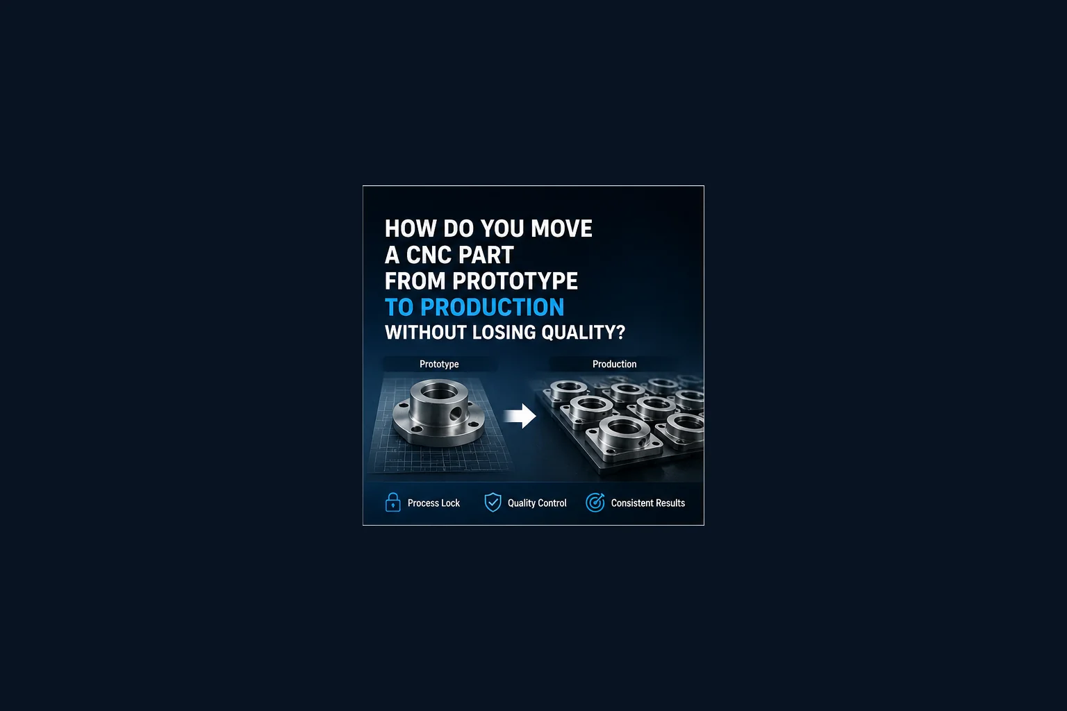
Moving a CNC part from prototype to production is not a simple matter of ordering more pieces. Prototype manufacturing proves that a design can be made, but production requires the same part to be made repeatedly, predictably, economically, and with controlled quality across different machines, operators, material lots, tooling cycles, finishing batches, inspection shifts, packaging conditions, and delivery dates.
Many quality problems appear only after volume increases. A prototype may be produced by one experienced machinist using extended cycle time, manual fitting, frequent measurement, selective material, and individual correction. These methods can produce an acceptable sample but may not represent a stable production process. When the order changes from five parts to five hundred, uncontrolled variation in tooling, fixturing, temperature, raw material, heat treatment, coating, and inspection becomes visible.
A successful transition requires a controlled manufacturing route. The design must be reviewed and frozen, critical-to-quality features must be identified, process capability must be evaluated, fixtures and gauges must be qualified, finishing requirements must be standardized, first articles and pilot batches must be approved, and all subsequent changes must be documented.
RapidMFGPro evaluates prototype-to-production projects from a supplier-matching perspective. The review considers part geometry, material, tolerance, process route, quantity, equipment, fixture investment, special processes, inspection, documentation, packaging, and production schedule before identifying suppliers whose machining and quality capabilities match the actual project.
This guide explains how engineers, product teams, purchasing managers, and manufacturing suppliers can move CNC parts from prototype to production without losing quality.
Why Does Quality Change after the Prototype Stage?
Quality can change because production introduces more sources of variation than prototype manufacturing.
More Parts Create More Variation
A small prototype order may use one tool set, one material bar, one fixture setup, and one operator.
Production may include multiple tool replacements, material lots, shifts, machines, and finishing batches.
Manual Correction Becomes Impractical
A prototype part can be measured repeatedly and adjusted by hand.
Production requires process control rather than individual correction.
Cycle-Time Pressure Increases
Prototype machining often uses conservative feeds, multiple finish passes, and extended inspection.
Production introduces pressure to reduce machining and handling time.
Supply-Chain Complexity Increases
Heat treatment, anodizing, plating, grinding, painting, laser marking, and assembly may be performed by different suppliers.
Each handoff can introduce variation, delay, damage, or documentation errors.
| Prototype Condition | Production Condition | Main Risk |
|---|---|---|
| One experienced machinist | Multiple operators or shifts | Different setup and inspection habits |
| One material lot | Repeated material purchases | Property, color, or residual-stress variation |
| Frequent manual measurement | Sampling-based inspection | Process drift may remain undetected |
| Slow conservative cycle | Optimized production cycle | Higher heat, tool wear, or deformation |
| Individual packaging | Batch packaging | Scratches, dents, and mixed revisions |
Define What the Prototype Was Intended to Prove
Before planning production, the team should identify what was actually validated during the prototype stage.
Form Validation
The prototype may have been used only to confirm size, shape, and visual appearance.
This does not prove that production tolerances or materials are correct.
Fit Validation
The prototype may have confirmed that mating components assemble.
One successful assembly does not prove interchangeability across production variation.
Functional Validation
The part may have passed load, motion, sealing, thermal, electrical, or environmental testing.
The test should be linked to specific dimensions and material properties.
Manufacturing Validation
A prototype proves manufacturability only when the intended production process was used.
A manually corrected sample does not validate a stable volume process.
Separate Prototype Intent from Production Intent
Prototype and production parts can use different manufacturing assumptions, but those differences must be identified.
Temporary Prototype Materials
A prototype may use 6061 aluminum even though production requires 7075, stainless steel, titanium, or a certified plastic.
Material changes can affect machining, strength, coating, and dimensions.
Simplified Prototype Features
Threads, surface finishes, internal passages, inserts, and cosmetic details may have been omitted from the prototype.
These features must be validated before production release.
Prototype Surface Treatment
A painted or uncoated prototype should not be used to approve the dimensional effect of anodizing, plating, powder coating, or passivation.
Production-intent finishing should be tested on representative parts.
Freeze the Design before Production Tooling
Production fixtures, gauges, programs, and inspection plans should not be finalized while the design is still changing.
Approve the 3D Model
The production model should include final geometry, hole locations, radii, chamfers, threads, and interfaces.
Suppliers should not work from uncontrolled model versions.
Approve the 2D Drawing
The drawing should define tolerances, GD&T, material, heat treatment, surface finish, and inspection requirements.
The drawing remains the primary acceptance document.
Control Revision Status
Every file should use a clear part number, revision, issue date, and approval record.
Obsolete revisions should be removed from production access.
Resolve Open Engineering Questions
Unresolved notes, optional dimensions, temporary features, and supplier assumptions should be closed before release.
Ambiguity becomes expensive after production begins.
Identify Critical-to-Quality Features
Critical-to-quality features are dimensions, properties, and conditions that directly affect function, safety, assembly, or customer acceptance.
Functional Fits
Bearing seats, dowel holes, sliding diameters, threads, press fits, and sealing grooves are commonly critical.
Their final condition should be inspected after all finishing.
Geometric Relationships
Position, profile, runout, perpendicularity, flatness, and concentricity may control assembly more than size.
Datum structures should match the actual product.
Material Properties
Hardness, conductivity, tensile strength, chemical resistance, and heat-treatment condition can be critical.
Material certificates alone may not prove final-part properties.
Cosmetic Requirements
Color, gloss, texture, grain direction, tool marks, and visible defects can be critical on customer-facing parts.
Cosmetic zones should be identified separately from hidden surfaces.
Remove Unnecessary Tight Tolerances
Production quality improves when the drawing controls what matters and allows reasonable variation elsewhere.
Review General Tolerance Blocks
An overly tight default tolerance can create unnecessary inspection and scrap.
General dimensions should use practical limits.
Focus on Functional Interfaces
Tight tolerances should remain on features that control assembly, motion, sealing, or alignment.
Hidden nonfunctional geometry can often use broader limits.
Use GD&T Where Appropriate
Position, profile, MMC, and datum-based controls can preserve function while allowing greater manufacturing freedom.
Redundant coordinate dimensions should be removed.
Standardize Material Requirements
Material variation can change dimensions, surface finish, cutting behavior, heat treatment, and coating appearance.
Specify Exact Grade
Generic notes such as aluminum, steel, or plastic are insufficient for controlled production.
The exact grade and equivalent standards should be stated.
Specify Temper or Condition
Aluminum temper, steel hardness, stainless condition, and plastic conditioning affect machining and final performance.
The full material condition should be controlled.
Specify Product Form
Plate, bar, extrusion, forging, casting, and molded stock have different residual stress and grain structure.
Product form should not change without approval.
Control Material Certification
Required certificates, heat numbers, lot traceability, and restricted-substance declarations should be identified.
Documentation requirements affect sourcing and lead time.
Evaluate Material Lot Variation
Even material supplied to the same grade can vary within the permitted chemical and mechanical range.
Machinability Variation
Tool wear, chip formation, burrs, heat, and surface finish can change between material lots.
Production cutting parameters should tolerate normal variation.
Residual-Stress Variation
Different plate, bar, and extrusion lots can move differently after material removal.
Thin-wall and flat parts may require stress-relieved stock.
Surface-Treatment Variation
Aluminum anodizing color and steel heat-treatment scale can vary by material lot.
Cosmetic production may require lot control and retained samples.
Define the Production Process Route
The production route should list each manufacturing and inspection stage in the order it will occur.
Primary Machining
Turning, milling, drilling, reaming, boring, and tapping create the main geometry.
Setup count and datum transfer should be minimized.
Secondary Precision Processes
Grinding, honing, lapping, EDM, and polishing may complete critical dimensions or surfaces.
Stock allowance should be included before these operations.
Special Processes
Heat treatment, plating, anodizing, passivation, powder coating, welding, and bonding require controlled suppliers.
The sequence affects dimensions and performance.
Final Inspection and Packaging
Final acceptance should occur after the last operation that can change the part.
Packaging should preserve the approved condition.
Compare the Prototype Route with the Production Route
Any difference between prototype and production methods should be treated as a new validation requirement.
Machine-Type Changes
A prototype made on a 5-axis machining center may be moved to 3-axis equipment with multiple setups for production.
Datum transfer and positional accuracy may change.
Fixture Changes
Prototype soft jaws may be replaced with a multi-part fixture or tombstone.
Clamping force and deformation should be revalidated.
Tooling Changes
Production may use coated carbide, form tools, combination drills, or custom cutters to reduce cycle time.
Tool marks and geometry should be checked.
Inspection Changes
Prototype parts may receive complete CMM inspection, while production may use functional gauges and sampling.
The reduced inspection plan must still detect process drift.
Design Production Fixtures Early
Fixtures influence repeatability, cycle time, deformation, tool access, and inspection consistency.
Use Functional Datums
The fixture should locate the part from the same datum structure used on the drawing and in assembly.
This reduces conflicting reference systems.
Control Clamping Force
Clamps should hold the part securely without moving thin walls, bores, or sealing faces.
Hydraulic and pneumatic pressure should be standardized.
Support Flexible Areas
Support nests, soft jaws, vacuum fixtures, and custom pads can reduce vibration and distortion.
Support should not trap chips.
Include Error-Proofing
Fixture features can prevent reversed, rotated, or wrong-revision loading.
Poka-yoke reduces operator-dependent mistakes.
Qualify the CNC Program
Production programs should be controlled, verified, and protected from unapproved changes.
Verify Toolpaths
Simulation should check collisions, remaining stock, overtravel, and tool reach.
Actual machine prove-out remains necessary.
Standardize Cutting Parameters
Feed, speed, engagement, coolant, tool overhang, and toolholder should be documented.
Operators should not rely on memory.
Control Program Revision
Every approved program should have a revision, release status, and backup.
Unauthorized edits should be restricted.
Record Offset Strategy
Tool wear and dimensional offsets should use controlled adjustment limits.
Excessive offset correction can hide tool or process failure.
Establish Tool-Life Control
Tool wear is one of the main reasons production dimensions and surface finish drift over time.
Define Replacement Limits
Tools should be replaced by part count, cutting time, wear measurement, or quality signal.
Waiting for visible failure creates scrap.
Monitor Critical Tools
Reamers, form tools, drills, taps, finish end mills, and boring bars directly control critical features.
Their life should be tracked separately.
Control Tool Regrinding
Reground tools can differ in diameter, geometry, coating, and length.
Regrind specifications should be standardized.
Use Wear Compensation Carefully
Small offsets can keep dimensions centered.
Large or frequent offsets indicate unstable tooling or process conditions.
Control Machine and Shop Temperature
Temperature affects machine geometry, tool length, material dimensions, and measurement results.
Machine Warm-Up
Spindles, ball screws, and structures change as the machine warms.
A consistent warm-up cycle improves repeatability.
Coolant Temperature
Coolant removes heat but can also heat or cool the part unevenly.
Stable coolant temperature supports tight tolerances.
Part Stabilization
Parts should reach a stable temperature before final measurement.
Warm parts can pass inspection and later move outside tolerance.
Inspection Environment
Precision gauges and CMMs may require a controlled room.
Measurement temperature should be recorded when necessary.
Standardize Deburring and Edge Finishing
Deburring affects dimensions, assembly, cleanliness, appearance, and coating performance.
Define Edge Breaks
Notes such as break all sharp edges should include a practical range where edge size matters.
Excessive manual deburring can change precision features.
Control Internal Burrs
Cross holes, threads, internal passages, and intersecting bores can retain hidden burrs.
Specific inspection or cleaning may be required.
Automate Where Possible
Brushing, tumbling, thermal deburring, abrasive flow, and robotic finishing reduce operator variation.
The process must remain compatible with tolerances and appearance.
Standardize Heat Treatment
Heat treatment can change hardness, strength, dimensions, straightness, color, and machinability.
Define the Material Condition
Hardness range, case depth, temper, aging condition, and mechanical properties should be specified.
General notes such as heat treat should be avoided.
Plan Machining Allowance
Parts that distort during heat treatment may require finish machining or grinding afterward.
Sufficient stock should remain.
Control Furnace Loading
Part orientation, batch size, support, heating rate, and quenching affect distortion.
Production loading should match qualification.
Verify Final Properties
Hardness, case depth, microstructure, and mechanical properties may require testing.
Certificates should be traceable to the batch.
Standardize Surface Treatment
Surface finishing often creates the largest difference between an acceptable machined prototype and a failed production part.
Define the Exact Finish
State anodizing type, plating chemistry, powder resin, paint system, passivation, blasting, polishing, or coating stack.
Generic finish names are not enough.
Control Coating Thickness
Coatings change holes, shafts, threads, fits, grooves, and surface roughness.
Final dimensions should be inspected after finishing.
Control Masking
Grounding pads, threads, bearing seats, sealing faces, and cosmetic boundaries should be dimensioned.
Mask transitions should have defined acceptance.
Control Color and Texture
Approved samples should use the production material, preparation, and finish.
Material-lot and batch variation should be considered.
Qualify External Special-Process Suppliers
Outsourced processes must be treated as part of the production system rather than as simple purchasing activities.
Confirm Process Scope
The supplier should be qualified for the exact material, specification, coating type, thickness, and part size.
Similar process names may hide different capabilities.
Confirm Capacity
Bath size, furnace size, oven size, rack quantity, line speed, and inspection capacity should support the production volume.
Limited capacity creates split lots and inconsistent batches.
Confirm Traceability
Process lot, date, operator, equipment, chemistry, furnace, and inspection records may require traceability.
The required level should be agreed.
Confirm Change Notification
Changes in chemistry, subcontractor, equipment, location, or process sequence should require approval where critical.
Silent changes create unverified risk.
Build a Production Control Plan
A control plan defines what is checked, how it is checked, when it is checked, and what action follows a failure.
Incoming Material Controls
Verify grade, certificate, dimensions, hardness, lot, and surface condition.
Material mix-ups should be prevented before machining.
In-Process Controls
Monitor critical dimensions, tool wear, machine offsets, first-off parts, and periodic samples.
Detection should occur before a large batch is completed.
Final Controls
Confirm dimensions, GD&T, finish, material condition, cleanliness, appearance, marking, and packaging.
Final inspection should use approved methods.
Reaction Plan
The plan should define containment, machine stop, segregation, reinspection, correction, and customer communication.
Operators should know what to do when a result approaches or exceeds a limit.
| Process Stage | Control Item | Typical Method | Reaction to Failure |
|---|---|---|---|
| Incoming material | Grade and lot | Certificate and material verification | Quarantine material |
| First machining operation | Datum and setup dimensions | Probe, micrometer, or CMM | Correct setup before continuing |
| Production machining | Critical bore or shaft | Bore gauge, air gauge, or micrometer | Stop and inspect since last accepted check |
| Surface treatment | Thickness and masking | Coating gauge and visual inspection | Segregate finishing lot |
| Final inspection | Complete drawing and function | CMM, gauges, and assembly test | Contain and review root cause |
| Packaging | Part protection and quantity | Visual check and count verification | Repack before release |
Create Standard Work Instructions
Work instructions translate the process plan into repeatable actions for operators, inspectors, and finishing teams.
Setup Instructions
Document fixture location, clamping force, datum cleaning, work offsets, tool list, and probe cycle.
Photos and diagrams reduce interpretation differences.
Machining Instructions
Define program revision, tool-life limits, coolant, part orientation, and in-process checks.
Critical notes should be visible at the machine.
Inspection Instructions
Define measurement points, gauges, datum setup, temperature, sampling, and recording.
Different inspectors should obtain comparable results.
Packaging Instructions
Define cleaning, drying, wrapping, orientation, tray loading, labels, and quantity per container.
Packaging should be revision controlled.
Perform First Article Inspection
First article inspection confirms that the complete production-intent process can produce the released drawing.
Use Production-Intent Equipment
First articles should use the intended machine type, fixture, program, tooling, material, and finishing route.
A special laboratory sample may not represent production.
Inspect the Complete Drawing
All dimensions, GD&T, notes, material, finishes, and special processes should be verified when required.
Ballooned drawings improve traceability.
Include Documentation
Material certificates, heat-treatment records, coating certificates, test reports, and inspection results should be included.
The package should match customer requirements.
Resolve Deviations before Release
Deviations should be approved, corrected, or incorporated through a formal drawing revision.
Temporary concessions should not become permanent undocumented practice.
Run a Pilot Production Batch
A pilot batch tests repeatability over more than one part and reveals variation that a single first article cannot show.
Use Representative Quantity
The batch should be large enough to include normal tool wear, multiple fixture positions, and realistic handling.
One or two pieces provide limited information.
Use Normal Production Speed
Pilot parts should use the intended cycle time and inspection frequency.
Slower special handling can hide future problems.
Include All Special Processes
Heat treatment, coating, marking, cleaning, and packaging should be included.
The complete route must be validated.
Record Process Data
Measure critical dimensions across the batch and record tool life, offsets, rejects, cycle time, and rework.
Data supports production release.
Evaluate Process Capability
Capability analysis determines whether normal process variation fits comfortably within the tolerance limits.
Check Process Centering
A process can have small spread but still run close to one specification limit.
Centering provides margin for drift.
Check Process Spread
Variation should be small relative to tolerance.
Tool wear, material, temperature, and fixture position should be represented.
Use Appropriate Capability Indices
Cp and Cpk may be used for stable short-term processes, while Pp and Ppk represent broader performance.
Required values should be agreed with the customer.
Confirm Measurement Capability
Capability results are unreliable when gauge variation is too large.
Gauge repeatability and reproducibility should be evaluated.
Validate Multi-Cavity and Multi-Position Fixtures
Production fixtures often machine several parts at once, but each fixture position can behave differently.
Inspect Every Position
The first qualification should include parts from each cavity or station.
One acceptable position does not validate the complete fixture.
Compare Clamping Conditions
Hydraulic flow, pneumatic pressure, support height, and chip buildup can vary across positions.
The fixture should produce consistent loading.
Track Cavity Identification
Parts can be marked or records can identify the fixture position.
Position traceability helps isolate recurring defects.
Validate More Than One Material Lot
A pilot batch from one material lot may not reveal the full production range.
Compare Machining Behavior
Monitor tool wear, burr formation, surface finish, and dimensional movement across lots.
Cutting parameters should remain stable.
Compare Heat-Treatment Response
Hardness and distortion can vary within grade limits.
Final machining allowance should accommodate normal variation.
Compare Surface-Finish Appearance
Anodized aluminum, polished stainless steel, and coated castings can vary between material lots.
Cosmetic acceptance should include realistic variation.
Validate Tool Changes
Production quality must remain stable before and after a tool is replaced.
New-Tool Condition
A new tool can cut differently from a tool near the end of life.
Both conditions should remain within the control range.
Replacement Repeatability
Presetting, tool length, diameter, runout, and holder cleanliness affect the first part after replacement.
A first-off check should be defined.
Reground Tool Variation
Reground tools may require separate offsets or qualification.
Mixing new and reground tools without control can create drift.
Validate Shift and Operator Changes
A process should not depend on one operator’s undocumented experience.
Standardized Setup
Different operators should load the part, clean datums, clamp, and start the cycle in the same way.
Work instructions should support this.
Standardized Measurement
Measurement force, gauge alignment, datum setup, and recording should be consistent.
Operator variation can appear as part variation.
Training and Qualification
Operators should be trained and qualified for critical processes.
Training records may be required for regulated projects.
Control Inspection Methods
Production quality depends on using the same measurement definition across prototype, supplier, customer, and final assembly.
Agree on Datum Simulation
CMM setup, fixture points, and free-state or restrained-state conditions should match the drawing.
Different datum simulations create different results.
Agree on Gauge Type
Micrometers, bore gauges, air gauges, CMMs, vision systems, and functional gauges do not measure in the same way.
The approved method should be stated.
Control Gauge Calibration
Instruments and masters should be calibrated and traceable where required.
Expired or damaged gauges should be removed from use.
Control Measurement Data
Inspection records should identify part number, revision, lot, date, instrument, operator, and result.
Data should support traceability and trend analysis.
Use Functional Gauges Where Appropriate
Functional gauges can confirm assembly requirements quickly and consistently during production.
Go/No-Go Gauges
Plug, ring, thread, and snap gauges provide fast acceptance for size and fit.
They do not provide actual measurement values.
Composite Gauges
Composite gauges can evaluate hole patterns and maximum-material-condition relationships.
They are useful for interchangeable assemblies.
Assembly Fixtures
Customer-representative fixtures can check mounting, alignment, insertion, and clearance.
The fixture should be calibrated and revision controlled.
Control Cosmetic Quality
Cosmetic acceptance often becomes more difficult in production because more parts, material lots, and finishing batches are compared together.
Define Cosmetic Zones
Class A visible surfaces should have stricter criteria than hidden or internal faces.
This prevents unnecessary rejection.
Use Approved Samples
Samples should define acceptable color, gloss, texture, grain, and defect level.
Samples should use production-intent material and finish.
Define Viewing Conditions
Lighting, distance, angle, and inspection time affect cosmetic judgment.
Controlled conditions reduce subjective disagreement.
Control Handling
Gloves, trays, soft fixtures, protective films, and clean tables reduce fingerprints, scratches, and dents.
Cosmetic control continues after finishing.
Control Part Cleanliness
Production parts may fail assembly or service because of chips, coolant, abrasive residue, plating chemicals, dust, or packaging contamination.
Define Cleanliness Level
The drawing or quality plan should state whether the part needs visual cleanliness, particle control, oil-free condition, or validated cleaning.
Clean is not a measurable requirement by itself.
Clean Internal Passages
Manifolds, cold plates, valves, and fluid components can retain chips and process solution.
Flushing, ultrasonic cleaning, borescope inspection, or particle testing may be required.
Protect after Cleaning
Clean parts should be handled and packaged to prevent recontamination.
Open containers and unprotected workstations can undo the cleaning process.
Validate Assembly before Full Production
Individual part inspection should be supplemented by assembly validation.
Check Interchangeability
Parts from different points in the tolerance range should assemble without selective matching.
Multiple mating samples should be used.
Check Assembly Force
Press force, insertion force, thread torque, and clamp preload should remain within acceptable limits.
Coating and surface finish affect the result.
Check Functional Performance
Rotation, sliding, leakage, electrical resistance, optical alignment, and thermal performance should be tested.
Dimensional conformity does not guarantee function.
Check Service and Maintenance
The assembly should allow required disassembly, cleaning, replacement, and repair.
Production finishes can change serviceability.
Establish Lot Traceability
Traceability links each delivered part to material, manufacturing, finishing, inspection, and packaging records.
Material Lot
Heat number, batch number, or supplier lot should be recorded where required.
Material traceability supports failure investigation.
Machining Lot
Production date, machine, fixture, program revision, and operator may be recorded.
The level should reflect risk and industry requirements.
Special-Process Lot
Heat-treatment, plating, anodizing, and coating batches should be traceable.
Split lots should not be mixed without identification.
Inspection Lot
Reports should identify the actual delivered batch.
Generic certificates should not replace lot-specific data when traceability is required.
Prevent Mixed Revisions and Mixed Lots
Production expansion increases the risk of mixing old drawings, old parts, different materials, or separate finish batches.
Physical Segregation
Different revisions and lots should use separate containers and locations.
Unidentified parts should be quarantined.
Clear Identification
Labels should include part number, revision, lot, quantity, status, and operation.
Barcodes can reduce manual entry errors.
Controlled Rework
Reworked parts should retain original and rework traceability.
Rework should not be returned to production without approval.
Establish Nonconformance Control
A production system should identify, contain, review, and disposition nonconforming parts consistently.
Immediate Containment
Suspect parts should be separated from accepted stock.
Production since the last accepted check may require review.
Technical Disposition
Parts may be reworked, repaired, accepted by deviation, downgraded, or scrapped.
Only authorized personnel should approve disposition.
Root-Cause Analysis
The investigation should identify why the process allowed the defect to occur and escape.
Correcting one part does not correct the process.
Corrective Action
Tooling, fixture, program, inspection, training, material, or supplier controls may need revision.
Effectiveness should be verified.
Control Engineering Changes after Production Release
Production quality can be lost when design or process changes are introduced without revalidation.
Design Changes
Geometry, tolerance, material, finish, and notes should use formal revision control.
Existing inventory and work in process should be reviewed.
Process Changes
Changes in machine, fixture, program, tool, heat-treatment route, coating supplier, or inspection method may affect quality.
Approval requirements should be defined.
Supplier Changes
Moving production to another supplier requires process and first-article validation.
Identical drawings do not guarantee identical results.
Temporary Changes
Temporary substitutions and deviations should have scope, expiration, and approval.
Temporary methods should not become undocumented standards.
Plan Production Capacity
Quality can deteriorate when demand exceeds machine, labor, inspection, or finishing capacity.
Machine Capacity
Available spindle hours should include setup, maintenance, tool changes, inspection, and expected downtime.
Quoted cycle time alone is not total capacity.
Fixture Capacity
The number of fixtures and fixture positions affects output and work in process.
Insufficient fixtures create rushed setups.
Inspection Capacity
CMM, gauge, and operator capacity must support the control plan.
Inspection bottlenecks can create unverified inventory.
Special-Process Capacity
Heat-treatment furnaces, plating baths, anodizing tanks, and coating ovens may limit delivery.
Capacity should be confirmed before ramp-up.
Plan Inventory and Work in Process
Inventory strategy affects traceability, damage risk, lead time, and response to engineering changes.
Limit Work in Process
Large unfinished batches can hide defects until many parts are affected.
Smaller controlled lots improve containment.
Separate Process Lots
Different machining, heat-treatment, and finishing lots should remain identifiable.
Mixing prevents root-cause isolation.
Review Obsolescence Risk
High inventory becomes a risk when design revisions are frequent.
Production quantity should reflect design maturity.
Validate Packaging for Production Volume
Prototype packaging may protect a few parts but become too slow, expensive, or inconsistent at production scale.
Prevent Part-to-Part Contact
Trays, dividers, sleeves, caps, bags, and custom inserts reduce scratches and dents.
Heavy parts should not shift during transport.
Support Thin and Flexible Parts
Thin walls, long shafts, and precision plates need local support.
Stacking pressure should not distort the part.
Protect Finished Surfaces
Anodized, plated, painted, polished, and ground surfaces require compatible packaging materials.
Sulfur, moisture, plasticizer, and adhesive contamination should be considered.
Perform Transport Validation
Drop, vibration, compression, humidity, and route testing can validate packaging.
Arrival condition should match final inspection.
Use a Controlled Ramp-Up Plan
Production should increase in stages rather than moving directly from a few prototypes to maximum volume.
Stage One: First Article
Confirm the complete drawing and documentation.
Correct all interpretation and process issues.
Stage Two: Pilot Batch
Confirm repeatability, tool life, fixture positions, finishing, inspection, and packaging.
Collect capability data.
Stage Three: Controlled Production
Increase quantity while maintaining higher inspection frequency.
Review trends and nonconformances closely.
Stage Four: Normal Production
Move to the approved control plan after capability and delivery are stable.
Continue periodic audits and monitoring.
| Stage | Main Objective | Required Evidence | Release Decision |
|---|---|---|---|
| Prototype | Validate design concept | Form, fit, and functional test | Approve design refinement |
| Design freeze | Control production definition | Released model and drawing | Approve tooling investment |
| First article | Validate complete process route | Full inspection and certificates | Approve pilot batch |
| Pilot production | Validate repeatability | Capability, cycle, and yield data | Approve controlled ramp-up |
| Controlled production | Confirm stable output | Trend data and approved lots | Approve normal production |
| Normal production | Maintain quality and delivery | Control-plan and audit records | Continue monitoring |
Track Production Quality Metrics
Production metrics reveal whether the process remains stable after initial approval.
First-Pass Yield
First-pass yield measures parts accepted without rework.
High final yield can hide excessive internal correction.
Scrap and Rework Rate
Defect type and process stage should be recorded.
Repeated rework indicates process weakness.
Capability Trends
Critical dimensions should be tracked over time.
Trend analysis identifies drift before tolerance failure.
Customer and Assembly Feedback
Fit, leakage, appearance, handling, and field performance should be linked back to production lots.
Internal inspection may miss application-specific problems.
Audit the Production Process
Audits verify that the approved process is still being followed.
Document Audit
Check drawings, programs, work instructions, inspection plans, calibration, and certificates.
Documents should match the current revision.
Process Audit
Observe setup, clamping, tool control, measurement, cleaning, and packaging.
Actual practice should match documented practice.
Product Audit
Select finished parts and verify dimensions, finish, marking, documentation, and packaging.
Product audits test the complete system.
Manage Multiple Suppliers Carefully
Using multiple suppliers can improve capacity and supply security, but it introduces process and appearance variation.
Use the Same Controlled Requirements
All suppliers should receive the same revision, material, finish, inspection, and packaging requirements.
Supplier-specific assumptions should be documented.
Compare First Articles
Each supplier should complete its own first-article and process validation.
Approval of one supplier does not approve another.
Control Cosmetic Matching
Different machining and finishing suppliers can produce visible shade and texture differences.
Parts used together may need one controlled finish source.
Monitor Supplier Performance
Quality, delivery, responsiveness, capacity, documentation, and corrective action should be reviewed.
Allocation can reflect performance.
When Should a Supplier Change Be Revalidated?
Supplier changes should be revalidated whenever the manufacturing or special-process route changes materially.
New Machining Supplier
New machines, fixtures, programs, and inspection systems create a new process.
First article and pilot validation are appropriate.
New Surface-Treatment Supplier
Coating color, thickness, masking, adhesion, and corrosion can change.
Production-intent samples should be approved.
New Material Source
A new mill, extruder, foundry, or resin supplier can change machinability and appearance.
Critical properties should be verified.
How Does RapidMFGPro Evaluate Production Readiness?
RapidMFGPro evaluates production readiness by connecting the released design with the process, capacity, supplier, inspection, and supply-chain controls required for repeatable delivery.
Design-Readiness Review
The review checks revision status, material, tolerances, GD&T, surface finish, cosmetic zones, and critical features.
Unclear or conflicting requirements are identified before supplier matching.
Process-Readiness Review
Machining route, fixture design, tooling, heat treatment, surface treatment, cleaning, marking, and packaging are reviewed.
Prototype-only methods are separated from production-intent methods.
Capacity Review
Machine hours, fixture quantity, inspection equipment, special-process capacity, labor, and delivery schedule are considered.
The supplier must support both quality and volume.
Supplier Matching
Suppliers are compared according to material experience, process capability, production equipment, quality systems, special-process control, metrology, traceability, packaging, and capacity.
A supplier suitable for five prototypes may not be the right supplier for recurring production.
Production Quality Review
The review confirms first-article scope, pilot-batch plan, control plan, capability, inspection, documentation, nonconformance handling, and change control.
These controls should be agreed before volume release.
How Should Production Suppliers Be Evaluated?
Production supplier evaluation should consider repeatability and capacity, not only whether one sample looks correct.
Similar-Production Experience
The supplier should have experience with similar material, tolerance, geometry, finish, and annual quantity.
Prototype experience alone may be insufficient.
Fixture and Automation Capability
Production may require dedicated fixtures, robotic loading, pallet systems, probing, and automated deburring.
Investment should match volume.
Quality-System Capability
Document control, calibration, traceability, nonconformance, corrective action, training, and internal audits should be evaluated.
Industry-specific certifications may be required.
Metrology Capability
CMM, optical systems, air gauges, profilometers, roundness testers, coating gauges, and functional fixtures may be needed.
Inspection capacity should support the production rate.
Continuity Planning
Backup machines, preventive maintenance, spare fixtures, tool supply, secondary processes, and disaster recovery should be considered.
Production continuity is part of quality risk.
What Common Transition Mistakes Cause Quality Loss?
Most prototype-to-production failures result from assumptions that were never converted into controlled requirements.
Approving Only One Perfect Prototype
One carefully corrected sample does not prove repeatability.
A pilot batch is needed.
Changing the Process without Revalidation
Different machines, fixtures, tools, material sources, and finish suppliers change the result.
Production-intent methods should be approved.
Skipping First Article Inspection
Small drawing errors and process assumptions can enter full production.
Complete first-article review reduces this risk.
Ignoring Measurement Capability
A supplier may report stable dimensions using a gauge that cannot resolve the tolerance reliably.
Measurement systems should be evaluated.
Adding Surface Treatment Late
Coating can change dimensions, color, fit, conductivity, and surface roughness.
The finish must be included in validation.
Ignoring Packaging
Parts can pass inspection and arrive scratched, bent, tarnished, or mixed.
Packaging must be qualified.
What Should Be Included in the Production RFQ?
A production RFQ should communicate more than geometry and quantity. It should define the complete supply and quality scope.
Released Technical Files
Provide the current 3D model, 2D drawing, part number, revision, and specification references.
Uncontrolled prototype files should be removed.
Quantity Profile
State first order, batch size, monthly demand, annual demand, and expected ramp-up.
Capacity and tooling decisions depend on the profile.
Quality Requirements
State first article, capability, sampling, CMM reports, material certificates, special-process certificates, gauge requirements, and traceability.
Documentation affects cost and lead time.
Delivery Requirements
State schedule, lot size, partial shipment, packaging, labeling, and destination.
Delivery structure affects production planning.
Change-Control Requirements
Identify which material, process, supplier, equipment, and location changes require approval.
The expectations should be established before award.
How Should the Final Production Decision Be Made?
Production release should occur only when the design, process, supplier, capacity, inspection, and documentation are ready to operate together.
Confirm Design Maturity
The model, drawing, material, tolerances, finish, and functional tests should be approved.
Open engineering issues should be closed.
Confirm Process Maturity
Fixtures, programs, tools, special processes, inspection, and packaging should be production intent.
Prototype-only corrections should be removed.
Confirm Quality Evidence
First articles, pilot batches, capability data, gauge studies, and assembly results should support release.
Exceptions should be documented.
Confirm Capacity and Supply Risk
Machine, labor, material, inspection, finishing, and delivery capacity should match demand.
Backup plans should exist for critical risks.
Confirm Change Control
The supplier and customer should agree on how future changes are requested, reviewed, validated, and documented.
Stable production depends on controlled change.
Frequently Asked Questions
These questions address common decisions when moving CNC parts from prototype to production.
Can the Prototype Supplier Also Handle Production?
Yes, when the supplier has suitable capacity, fixtures, process control, metrology, documentation, and special-process support.
Why Is a Pilot Batch Needed after First Article Approval?
A first article proves one process result. A pilot batch reveals repeatability, tool wear, fixture-position, material-lot, finishing, and packaging variation.
Should Production Use the Same Machine as the Prototype?
Not necessarily. A different machine can be used after the new process is validated through first articles and pilot production.
When Should Production Fixtures Be Built?
Production fixtures should be finalized after design freeze and before production-intent first-article validation.
How Can Production Tolerances Stay Consistent?
Use stable fixtures, controlled tooling, thermal management, in-process inspection, capability monitoring, calibrated gauges, and documented reaction plans.
Does Every Production Part Need Full Inspection?
Not always. Inspection frequency depends on feature criticality, process capability, risk, volume, and customer requirements.
When Is Revalidation Required?
Revalidation is commonly required after major design, material, machine, fixture, program, supplier, special-process, or inspection changes.
How Can Cosmetic Quality Stay Consistent?
Control material lots, surface preparation, approved samples, finishing batches, viewing conditions, handling, and packaging.
Conclusion
Moving a CNC part from prototype to production without losing quality requires more than increasing order quantity. The design must be frozen, critical features identified, materials standardized, fixtures and programs qualified, tooling controlled, special processes validated, first articles approved, pilot batches measured, capability demonstrated, and change control maintained. Inspection, traceability, cleanliness, cosmetic standards, packaging, and capacity must also scale with volume. RapidMFGPro supports this transition by reviewing production readiness and matching projects with suppliers whose machining, finishing, metrology, documentation, and capacity fit the actual production requirement.
Need Help Reviewing a Custom Part?
Share your CAD file and requirements to request supplier matching. Supplier capability and commercial terms must be verified before order placement.
Request Supplier Match