Time to read: 23 min
How to Ensure the Quality of Your CNC-Machined Parts
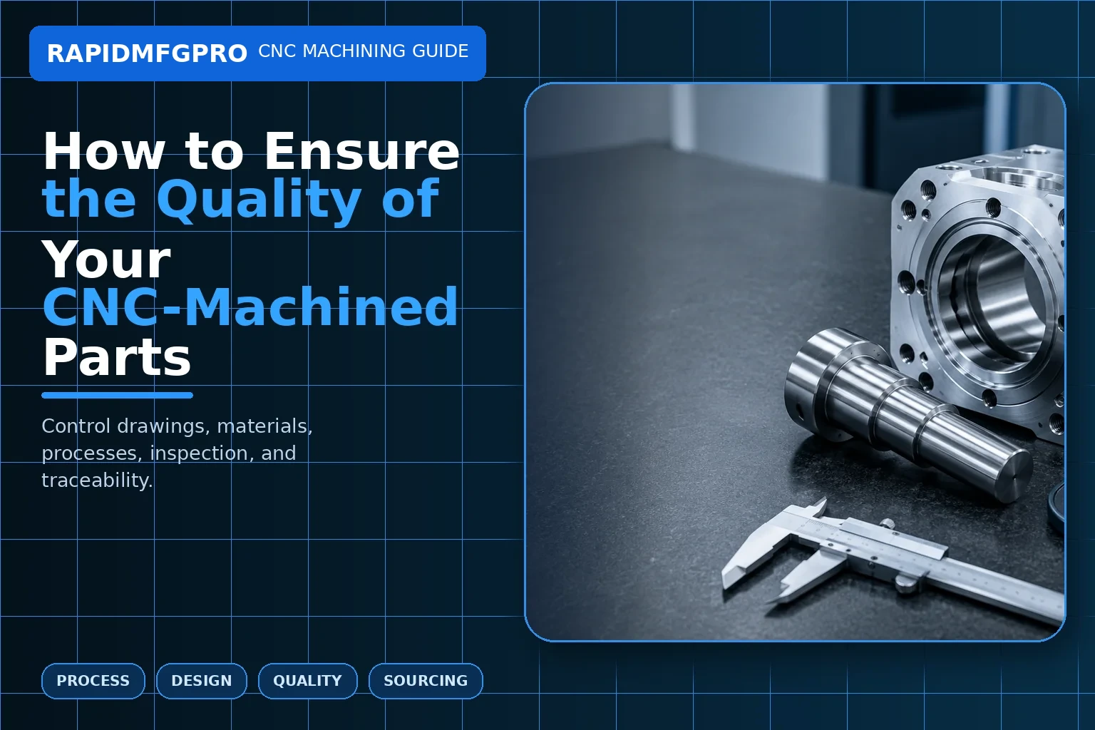
Direct answer: To ensure the quality of CNC-machined parts, control quality before, during, and after machining. Begin with a complete drawing and realistic tolerances. Review manufacturability, verify material and revision, approve the process plan, control tools and fixtures, inspect critical features with suitable equipment, manage secondary processes, and define how nonconforming parts will be handled. Final inspection alone cannot compensate for unclear requirements or an unstable process.
Quality is often discussed as if it were a single inspection step. In reality, a part can pass several dimensions and still fail because the wrong alloy was used, the datum was misunderstood, a coating tightened a bore, an internal burr remained, or a supplier mixed revisions. This guide explains a practical quality-control system and how RapidMfgPro helps buyers identify independent suppliers whose inspection and process controls align with the project.
What Does Quality Mean for a CNC-Machined Part?
Quality means conformity to the complete requirement
A quality part matches the drawing, 3D model, material, heat treatment, finish, appearance, cleanliness, documentation, packaging, and quantity. Dimensional accuracy is one element. Functional quality may also include leak tightness, electrical contact, hardness, corrosion resistance, surface integrity, or assembly fit.
The requirement must be measurable. “High precision,” “perfect finish,” and “no defects” are not useful acceptance criteria. Define tolerance, roughness, color range, scratch standard, particle limit, test pressure, or reference sample as appropriate.
Quality level should follow application risk
A fixture plate for internal shop use may need basic dimensional inspection. A medical diagnostic housing, aircraft replacement component, robot joint, or pressure manifold may require deeper documentation and traceability. Applying the same quality plan to every part either wastes cost or leaves risk uncontrolled.
Classify features by consequence: safety-critical, functional, assembly, cosmetic, and noncritical. The inspection plan can then focus resources on the characteristics that matter.
| Quality dimension | Example requirement | How it is verified | Failure consequence |
|---|---|---|---|
| Material | 6061-T6 aluminum with certificate | Certificate review, identification, PMI if needed | Strength, corrosion, or finish response may differ |
| Dimensional | Ø20 H7 bearing bore | Bore gauge, air gauge, CMM | Loose or seized bearing fit |
| Geometric | Hole position relative to datums | CMM or functional gauge | Assembly misalignment |
| Surface | Ra 1.6 µm sealing face | Roughness tester and visual inspection | Leakage or accelerated wear |
| Finish | Type II black anodize with masked threads | Certificate, thickness, visual and fit check | Corrosion, color, or assembly problem |
| Cleanliness | No chips in internal channels | Flush, borescope, particle or flow test | System contamination or blockage |
How Should Drawings and Specifications Be Prepared?
Use the 3D model for shape and the drawing for control
The 3D model defines nominal geometry. The drawing should define critical dimensions, datums, geometric tolerances, threads, surface roughness, material, heat treatment, coating, edge conditions, inspection notes, and revision. If model-based definition is used, the supplier must understand which annotations are authoritative.
Do not duplicate dimensions inconsistently between files. If the model and drawing disagree, production stops or the supplier makes an assumption. Identify the governing document and revision.
Use realistic tolerances and logical datums
Tighten only features that affect fit, sealing, motion, alignment, or function. A tight general tolerance on every dimension increases cost and rejection risk. Large thin parts, deep pockets, and plastics cannot hold the same numbers as small rigid steel blocks under all conditions.
Datums should represent how the part is located in assembly or inspection. Position, profile, runout, perpendicularity, and flatness should be used to communicate relationships clearly. Avoid overconstraining the drawing with conflicting controls.
Why Is DFM Review Part of Quality Assurance?
DFM identifies risks before material is cut
Design-for-manufacturability review checks tool access, corner radii, depth, wall thickness, workholding, distortion, stock availability, thread engagement, coating allowance, and inspection feasibility. A supplier should raise questions before quoting or production.
For example, a thin enclosure may warp when a large pocket is removed. A blind thread may not have enough runout. A seal groove may have an impossible sharp corner. Anodizing may close a close-fit bore. Early review prevents these predictable defects.
Approved changes must be controlled
A verbal DFM suggestion is not permission to alter a design. The engineer should approve a revised drawing or documented deviation. The supplier must link the approved revision to the program, traveler, inspection plan, and certificates.
Uncontrolled “shop improvements” can change function. Even a helpful radius change can interfere with a mating component.
| DFM risk | Possible defect | Preventive action | Quality evidence |
|---|---|---|---|
| Thin wall next to deep pocket | Wall taper or distortion | Staged machining, support, design thickening | Wall measurement and free-state inspection |
| Tiny internal corner | Tool breakage or uncut material | Increase radius or define relief | Profile inspection |
| Heat treatment after machining | Warping or size change | Leave finish allowance; inspect after heat | Hardness and final dimensional report |
| Coated thread or bore | Assembly interference | Mask or compensate dimension | Post-finish gauge check |
| Hidden cross-hole burr | Fluid contamination | Defined deburring and cleaning route | Borescope/flow/cleanliness result |
How Are Material and Revision Controlled?
Verify material identity from receipt to shipment
Material control begins with the purchase specification. The supplier should receive stock with identification and certificates when required. Heat number, lot number, or batch traceability may be recorded for critical projects. Positive material identification can be added when consequence or regulation justifies it.
Material should remain identified after cutting. Mixed aluminum, stainless, or plastic grades can look similar. Scrap tags and traveler links help prevent substitution.
Prevent mixed revisions and obsolete programs
Released drawings and models should be stored under controlled names. CNC programs, setup sheets, fixtures, and inspection plans must correspond to the same revision. When a design changes, obsolete files should be removed from active production access.
First-article approval is revision-specific. A minor change to a hole, finish, or material may require partial or complete revalidation.
How Is the Machining Process Controlled?
Stable setup and tooling prevent variation
Workholding must locate the part consistently and resist cutting forces without distortion. Fixtures should be cleaned, maintained, and verified. Soft jaws and locating pins wear. Clamping force can deform thin or plastic parts.
Tool selection, feeds, speeds, coolant, and cutting sequence affect heat, burrs, finish, and tool life. The supplier should define when inserts are changed and how offsets are adjusted. Waiting for a tool to fail can produce gradual dimensional drift before failure becomes obvious.
In-process checks catch problems before the batch is complete
Operators can check critical dimensions after roughing, before removing the part, or at defined intervals. Machine probes may verify stock, fixture location, and some features. Statistical process control can monitor stable high-volume characteristics.
In-process measurement should not become uncontrolled adjustment. Offset changes need limits and records for critical production. The process should distinguish normal tool-wear compensation from a signal that the fixture, material, or program is wrong.
Which Inspection Methods Should Be Used?
Use the instrument that matches the characteristic
Calipers provide quick general measurements but are not suitable for every tight tolerance. Micrometers measure outside dimensions. Bore gauges and air gauges measure internal diameters. Height gauges and surface plates evaluate planar features. CMMs evaluate position, profile, and complex datum relationships. Optical systems help with small edges and profiles.
Surface roughness testers, hardness testers, thread gauges, pin gauges, radius gauges, and functional fixtures address specific characteristics. A report is only as reliable as the method, calibration, fixturing, and operator technique.
Define sampling and report scope
First article inspection usually checks all drawing characteristics on initial production or after significant change. Routine production may use 100% inspection for critical features and sampling for stable noncritical dimensions. The plan should consider batch size and consequence.
Specify whether the buyer needs a simple dimensional report, ballooned FAI, CMM data, material certificate, coating certificate, hardness result, capability study, or control plan. “Inspection report required” is too vague.
| Characteristic | Preferred method | Common mistake | Improvement |
|---|---|---|---|
| Outside diameter | Micrometer or comparator | Using calipers at tight tolerance | Use instrument with adequate resolution and method |
| Bore fit | Bore gauge, air gauge, CMM | Checking only with one pin | Measure size and form as needed |
| Hole position | CMM or functional gauge | Measuring edge distances independently | Evaluate position relative to datums |
| Flatness | Surface plate/indicator or CMM | Measuring thickness only | Inspect free-state surface condition |
| Thread | GO/NO-GO gauge or pitch measurement | Trying a random screw | Use specified class and calibrated gauge |
| Cosmetic finish | Defined visual standard | Inspecting under inconsistent lighting | Use controlled light, distance, angle, and sample |
How Are Surface Finish and Secondary Processes Controlled?
Inspect before and after finishing
A part may meet dimensions before coating and fail afterward. Critical threads, bores, and contact surfaces should be checked in the finished condition or masked. Coating thickness, color, adhesion, corrosion performance, and appearance may require separate evidence.
Heat treatment and welding can distort parts. Grinding after heat treatment may be needed. The inspection route should include hold points so defects are found before expensive finishing.
Cleaning and handling protect the final part
Chips, coolant, abrasive media, fingerprints, and packaging debris can make a dimensionally correct part unusable. Define cleaning based on application. Internal passages may need flushing or borescope inspection. Optical and medical parts may need protected clean handling.
Packaging should separate parts, protect cosmetic faces, prevent corrosion, and preserve identification. Damage during shipping is a quality failure even if manufacturing was correct.
How Should Nonconforming Parts Be Managed?
Contain, identify, and communicate the problem
Suspect parts should be segregated so they cannot ship accidentally. The supplier should identify quantity, affected feature, actual result, drawing requirement, production stage, and possible cause. Buyers should be notified according to agreed terms.
Rework, repair, use-as-is, and scrap are different dispositions. Rework returns the part to the drawing. Repair changes the part through an approved method. Use-as-is requires authorized deviation. The supplier should not make these decisions alone when customer approval is required.
Corrective action should address process cause
Replacing defective pieces is containment, not corrective action. The root cause may involve drawing ambiguity, fixture wear, tool life, material mix, wrong offset, inspection method, or revision control. The action should prevent recurrence and verify effectiveness.
For recurring production, trend data can reveal gradual deterioration. A capable supplier learns from nonconformance instead of hiding it.
| Nonconformance step | Required information | Buyer decision | Supplier responsibility |
|---|---|---|---|
| Containment | Affected lot, quantity, location | Request stop-ship or sorting | Segregate and protect traceability |
| Evaluation | Requirement versus actual result | Assess function and risk | Provide accurate measurement and evidence |
| Disposition | Rework/repair/use-as-is/scrap proposal | Approve when authorization is required | Execute only approved method |
| Root cause | Process and system analysis | Review adequacy for critical issues | Identify true cause, not only operator error |
| Corrective action | Action, owner, date, verification | Confirm closure criteria | Implement and verify effectiveness |
How Can RapidMfgPro Support CNC Part Quality?
Match quality capability to the project
When buyers submit the drawing, model, material, quantity, finish, inspection, documentation, and application requirements, RapidMfgPro can help identify independent suppliers whose machines, metrology, quality systems, and process experience appear suitable.
A standard prototype supplier may not be appropriate for full traceability, tight optical alignment, medical cleaning, or aerospace documentation. Matching should consider quality evidence and risk, not only machining capacity.
Keep responsibilities transparent
The selected supplier is responsible for manufacturing and inspection under the agreed purchase terms. The buyer approves the technical requirements, supplier qualification, reports, and deviations. RapidMfgPro supports the requirement review and supplier search but should not imply ownership of third-party factories or quality certificates.
For effective comparison, buyers can ask RapidMfgPro to collect consistent information: proposed process route, FAI scope, material certificate, outside processors, inspection equipment, lead time, and nonconformance procedure.
How Should Quality Planning Change from Prototype to Production?
Prototype quality confirms design and basic process feasibility
Prototype inspection should focus on the features needed for testing. A full production control plan may be unnecessary for a one-off concept, but material, critical dimensions, finish, and assembly interfaces still need verification. If the prototype is used for regulatory, fatigue, pressure, or thermal validation, the material and process route must reflect the intended condition.
Prototype deviations should be documented. Hand fitting, manual polishing, or substituted material can make a prototype function while hiding production risk. The test report should state these differences.
Pilot and production quality confirm repeatability
A pilot batch evaluates fixtures, tool life, inspection frequency, operator instructions, outside processing, packaging, and delivery. The supplier should use the intended production route. Process capability may be studied for critical characteristics once the process is stable.
Production control plans identify inspection points, sample size, reaction limits, and records. Change control becomes more important because a new material lot, tool, fixture, program, machine, or processor can affect results.
What Should a CNC Supplier Quality Audit Include?
Review the management system and shop-floor execution
Audit document control, contract review, purchasing, material identification, calibration, training, maintenance, nonconformance, corrective action, and record retention. Then trace one real job from drawing receipt through material, program, setup, inspection, finishing, and shipment.
Look for alignment between procedures and practice. A written calibration policy is useful only if gauges show current status and overdue tools are blocked. A revision-control procedure is useful only if operators cannot accidentally load obsolete programs.
Focus the audit on project-specific risks
For a thin-wall aluminum housing, review distortion control and anodizing allowances. For a turned shaft, review runout measurement, heat treatment, and grinding. For a medical fluid part, review cleaning, internal burr control, and traceability. For optical hardware, review cosmetic handling and datum inspection.
Generic audits can miss these issues. Prepare project-specific questions and request objective evidence.
How Can Measurement-System Errors Be Reduced?
Use measurement-system analysis for critical characteristics
Repeatability is variation when the same operator measures the same part repeatedly. Reproducibility is variation between operators or setups. Gauge R&R studies can show whether the measurement system is suitable for a production characteristic.
For small batches, a formal study may not be justified, but the principle still applies: the gauge and method should resolve the tolerance with adequate margin. If measurement variation consumes a large share of tolerance, accept/reject decisions become unstable.
Control environment, fixturing, and measurement definition
Temperature, cleanliness, part stabilization, probe force, surface finish, and fixture restraint affect measurement. A large aluminum plate measured warm near the machine may not match a stabilized CMM result. A flexible ring measured in a clamp may appear round while the free part is oval.
Inspection instructions should define datum setup, measurement points, free-state condition, and any filtering or best-fit rules. Buyer and supplier should agree on methods before a dispute occurs.
How Should Packaging and Delivery Quality Be Verified?
Protect dimensions, finishes, and identification
Use separators, caps, sleeves, anti-corrosion protection, clean bags, or custom trays according to risk. Threads and precision bores may need plugs. Cosmetic anodized faces should not rub together. Heavy parts need packaging that prevents movement and edge impact.
Labels should identify part number, revision, quantity, batch, and traceability as required. Certificates should match the shipped lot.
Perform a final release review
Before shipment, confirm quantity, final inspection status, certificates, finish, cleanliness, packaging, and destination requirements. A final checklist prevents accepted parts from being mixed with samples, rework, or obsolete revisions.
Receiving inspection should also be risk-based. Buyers may verify identity, packaging, key dimensions, and documentation rather than repeat every supplier measurement. Feedback from receiving and assembly should return to the supplier scorecard.
How Do You Build a Part-Specific CNC Quality Plan?
Convert drawing risks into process controls
Begin by ballooning the drawing and classifying each characteristic. Mark safety or regulatory features, functional interfaces, assembly features, cosmetic surfaces, and noncritical dimensions. For every critical feature, identify the operation that creates it, the likely failure mode, the process control, the inspection method, the frequency, and the reaction plan.
For a robot joint housing, the plan may control bearing-bore size, coaxiality, motor-face perpendicularity, encoder-mount position, and cleanliness. For an EV cooling component, it may control channel depth, sealing flatness, port threads, brazing or welding, leak testing, and internal cleanliness. The quality plan should reflect the real product rather than use a generic checklist.
Assign evidence and approval at each hold point
Define what must be approved before the next costly operation. Material identity should be confirmed before machining. Rough stock allowance should be checked before heat treatment. Critical dimensions may be reviewed before coating. Leak testing and final inspection should occur after all operations that can affect the result.
Assign who reviews the evidence: supplier inspector, buyer engineer, or third party. State whether records are submitted with every shipment or retained for audit. This prevents certificates and reports from becoming an afterthought.
How Can Incoming and Assembly Feedback Improve Quality?
Use receiving inspection to verify the supplier system
Receiving inspection can confirm identity, quantity, packaging, certificates, visual condition, and selected critical dimensions. It should not automatically repeat the entire supplier report unless risk justifies it. Compare receiving results with supplier data and investigate systematic differences in measurement method.
Track damage, corrosion, mixed revisions, missing documents, and packaging failures as quality issues. These problems affect production even if the machined dimensions are acceptable.
Feed assembly and field results back into drawing and control plans
Assembly technicians often detect tight fits, burrs, cable interference, cosmetic problems, or difficult fastener access. Record these observations with part revision and lot number. Determine whether the issue comes from machining variation, tolerance stack, design, finish, or assembly method.
Field failures should trigger a structured review of material, process history, loading, environment, and mating parts. The result may require a supplier corrective action, a drawing change, or both. Quality improves when information flows beyond final inspection.
For complex assemblies, link supplier lot data to assembly and test results. If a leakage, alignment, or wear problem appears later, this traceability helps separate part variation from assembly method or operating conditions. Even a simple batch number and revision record can make root-cause analysis far more effective.
Conclusion
CNC part quality is created by clear requirements, manufacturable design, controlled material and revisions, stable machining, suitable inspection, managed finishing, and disciplined nonconformance handling. Final inspection is only one part of the system. Buyers should define critical features and request evidence proportional to risk. RapidMfgPro can help identify independent suppliers with relevant machining and quality capability, while the buyer and selected manufacturer retain clear responsibility for approval, production, and acceptance.
Need Help Reviewing a Custom Part?
Share your CAD file and requirements to request supplier matching. Supplier capability and commercial terms must be verified before order placement.
Request Supplier Match