Time to read: 6 min
Robotic Arm Component Manufacturing: Process Selection and Sourcing Guide
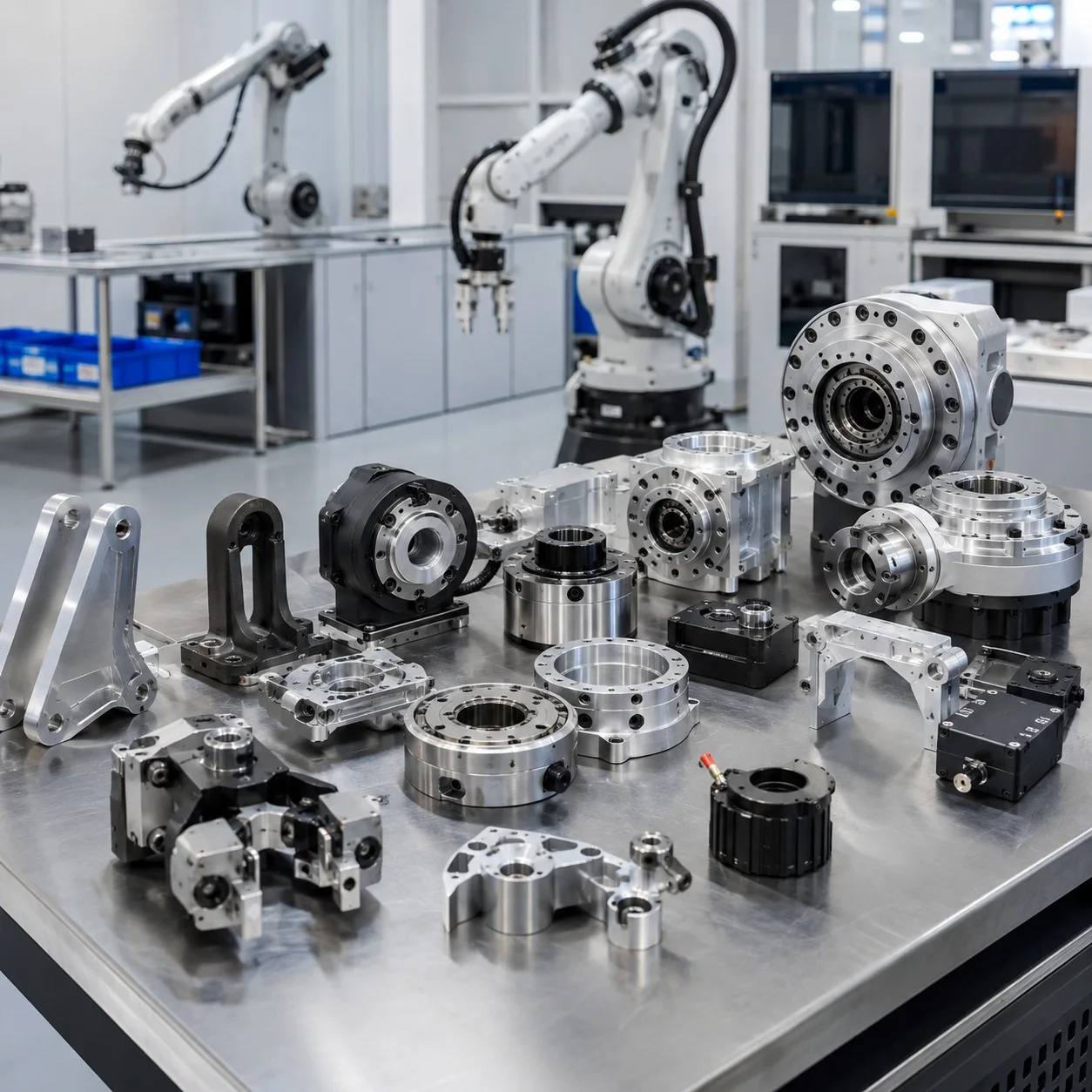
Robotic arm performance depends on a chain of mechanical components that must move accurately, carry repeated loads, and maintain alignment over thousands or millions of cycles. Housings, joint bodies, shafts, bearing seats, motor mounts, end-effector plates, brackets, and covers may look like separate parts, but they function as one motion system. A sourcing decision that focuses only on unit price can create assembly problems, excess backlash, vibration, or inconsistent motion later.
This guide explains how to select manufacturing processes for robotic arm components, which design details deserve the most attention, and what information to include in an RFQ. It also shows how RapidMfgPro can help engineers compare CNC machining, sheet metal fabrication, 3D printing, and other manufacturing routes for prototype and production projects.
Start with the Function of Each Robotic Arm Component
The first step is to identify what each component does inside the mechanism. A joint housing may position bearings and support a gearbox. A shaft may transmit torque and locate rotating elements. A motor plate may control alignment between a motor and reducer. A bracket may carry static load while also resisting vibration. These functions determine the most important dimensions and the most suitable process.
For example, a cosmetic cover may tolerate wider dimensions and can often be made by sheet metal fabrication or 3D printing. A bearing housing needs accurate bores, controlled concentricity, and stable mounting faces, making CNC machining more appropriate. A shaft with shoulders, grooves, and threads is usually better suited to CNC turning. Separating functional requirements from visual requirements prevents unnecessary cost.
Choose the Manufacturing Process by Geometry and Volume
CNC Machining for Structural and Alignment-Critical Parts
CNC machining is commonly used for robotic joint housings, gearboxes, bearing carriers, end-effector plates, and precision brackets. It can produce accurate holes, pockets, mounting faces, threaded features, and locating shoulders in aluminum, stainless steel, steel, titanium, and engineering plastics.
Three-axis machining is suitable for many plates and housings. Four-axis machining can reduce repeated setups for cylindrical bodies or parts with features around several sides. Five-axis machining is useful for complex lightweight structures, angled interfaces, and components that would otherwise require multiple fixtures.
CNC Turning for Shafts, Pins, and Rotational Components
Robotic arms use many turned components, including shafts, spacers, bushings, threaded adapters, bearing sleeves, and cable-routing collars. CNC turning is efficient when the main geometry is rotational. Live tooling can add flats, cross holes, keyways, and off-axis features without moving the part to a separate milling machine.
Sheet Metal Fabrication for Covers and Frames
Sheet metal fabrication is often suitable for protective covers, control boxes, internal trays, sensor brackets, and lightweight frames. Laser cutting and bending can produce low-volume parts quickly, while hardware insertion and welding support assembly-ready enclosures.
3D Printing for Early Validation
3D printing can shorten the early development cycle for cable guides, sensor mounts, ergonomic covers, gripper fingers, and fit-check models. It is especially useful before committing to machined metal parts. Engineers can test reach, collision clearance, wiring paths, and assembly sequence, then update the CAD model before production.
Control Interfaces, Not Every Dimension
Robotic assemblies often become expensive because drawings apply tight tolerances everywhere. A better strategy is to identify the interfaces that influence motion and assembly. These usually include bearing seats, gearbox pilot diameters, motor locating features, shaft diameters, dowel holes, and mounting faces.
General exterior dimensions can often use standard machining tolerances, while critical fits receive specific limits. Hole position may be more important than hole diameter for a bolted pattern. Flatness may matter on a motor plate, while parallelism may matter between two bearing seats. Clear datum selection helps the manufacturer inspect the part in the same way the engineer intended.
- Define bearing and bushing fits directly on the drawing.
- Identify datums that reflect the actual assembly sequence.
- Use geometric tolerances only where they protect function.
- Separate cosmetic surfaces from precision interfaces.
- State whether threaded holes require inserts, thread locking, or specific engagement length.
Select Materials Around Load, Weight, and Environment
Aluminum is widely used for robotic housings and brackets because it offers a useful balance of weight, stiffness, machinability, and finish options. Grades such as 6061 are common for general structures, while higher-strength grades may be considered where weight is critical. Steel is useful for shafts, gears, pins, and highly loaded interfaces. Stainless steel may be preferred in wet, clean, food-processing, or laboratory environments.
Engineering plastics can reduce weight, noise, and friction in guards, guides, and low-load components. POM is often considered for wear surfaces and dimensional stability. Nylon can be suitable for guides and covers but requires attention to moisture absorption. PEEK is reserved for demanding temperature, chemical, or performance requirements because of its higher material cost.
The correct material choice should be based on load, stiffness, fatigue, environment, finish, and availability—not only maximum strength. In many robotic parts, stiffness and interface stability are more important than ultimate tensile strength.
Plan Surface Finish and Post-Processing Early
Surface finish affects corrosion protection, wear, appearance, electrical contact, and assembly. Anodizing is common for aluminum housings and brackets. Hard anodizing may be considered for wear surfaces, but coating thickness must be included in fit calculations. Black oxide can provide a dark appearance on steel with limited dimensional change, while plating or passivation may be selected for specific corrosion requirements.
Masking notes should identify bearing bores, grounding points, threaded holes, and precision interfaces that must remain uncoated. If a finish is chosen after machining is complete, critical dimensions may no longer assemble correctly.
Prepare a Better RFQ for Robotic Components
A complete RFQ helps the manufacturing team understand both part geometry and project priorities. Include the 3D CAD file, a dimensioned drawing, material grade, quantity, finish, inspection requirements, and target schedule. Also explain whether the parts are prototypes, validation units, or production components.
For assemblies, provide a simple exploded view or interface drawing. It can reveal how parts relate to bearings, motors, gearboxes, sensors, and fasteners. If only a few dimensions are critical, mark them clearly instead of applying a general tight tolerance to the entire drawing.
Prototype, Validate, and Scale with Less Risk
A practical robotics workflow often begins with 3D-printed fit checks or quickly machined prototypes. After motion and assembly testing, the design can be revised for easier manufacturing, better tool access, fewer setups, or reduced material removal. The validated design can then move into low-volume or repeat production with a stable inspection plan.
RapidMfgPro can review robotic component CAD files, compare suitable manufacturing processes, and coordinate prototype-to-production requirements. By focusing on interfaces, materials, tolerances, and assembly risks early, engineering teams can reduce redesigns and obtain parts that support accurate, reliable robotic motion.
Need Help Reviewing a Custom Part?
Share your CAD file and requirements to request supplier matching. Supplier capability and commercial terms must be verified before order placement.
Request Supplier Match