Time to read: 21 min
What Is CNC Milling and Why Is It Important for Custom Parts?
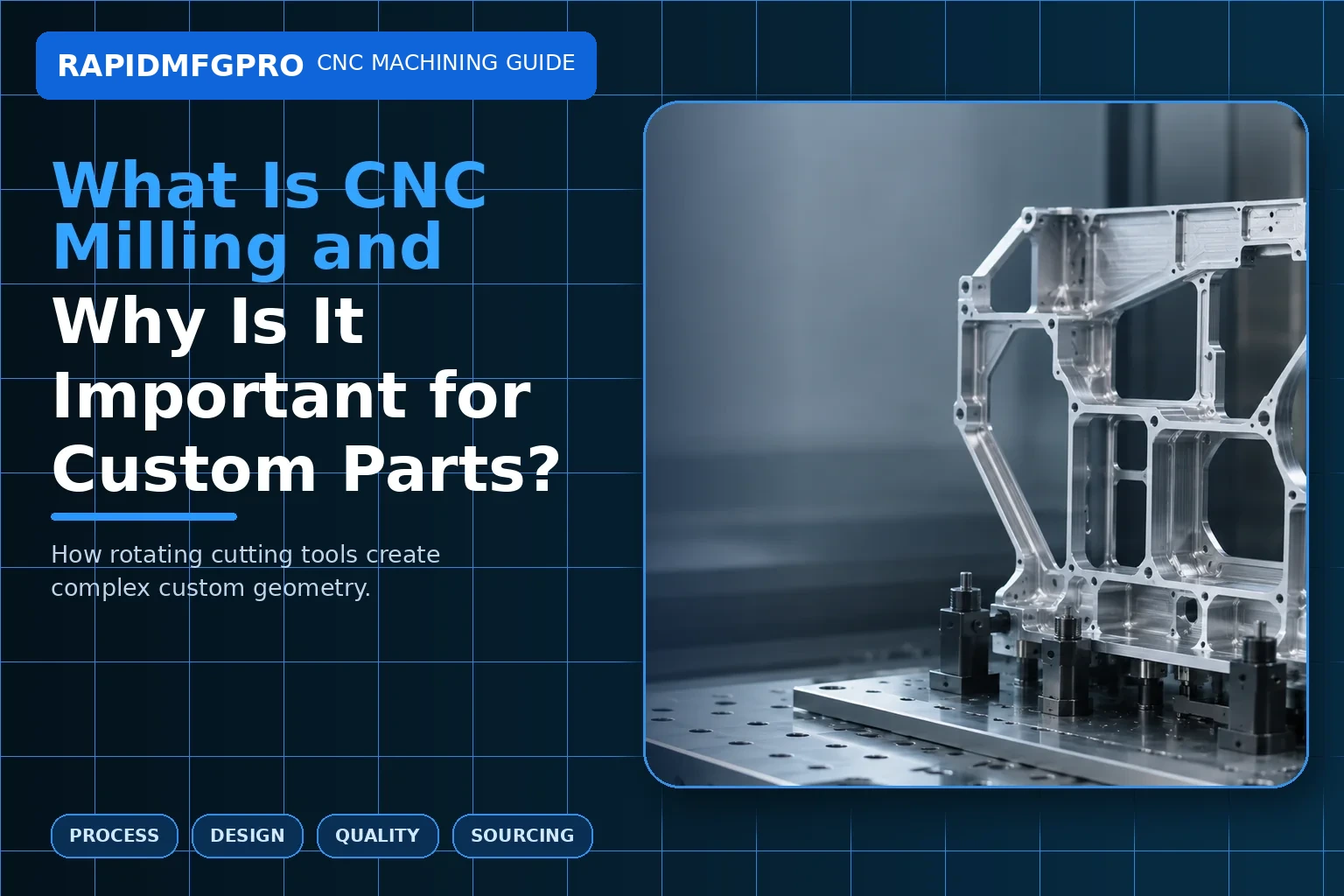
Direct answer: CNC milling is a machining process in which a rotating cutting tool removes material from a stationary or controlled workpiece. It is important for custom parts because it can produce accurate faces, pockets, slots, holes, threads, contours, and multi-sided features directly from CAD data without a production mold. Milling is commonly used for prototypes, brackets, housings, plates, manifolds, fixtures, optical bases, robot components, and low-volume production parts.
The usefulness of milling does not come only from machine accuracy. It comes from the combination of tool access, fixture planning, datum control, material behavior, and inspection. A design that looks straightforward in CAD may require several setups, long tools, thin-wall support, or special workholding. This guide explains how CNC milling works, why it matters for custom parts, and what information helps RapidMfgPro identify independent suppliers with appropriate milling capability.
What Is CNC Milling?
A rotating cutter creates the part geometry
In CNC milling, the spindle rotates a cutting tool while machine axes position the tool and workpiece relative to each other. End mills, face mills, drills, reamers, thread mills, chamfer tools, ball nose cutters, and form tools remove material in planned passes. The machine may move along three linear axes or include one or two rotary axes.
Unlike turning, where the workpiece usually rotates, milling is well suited to prismatic shapes: parts defined by flat faces, pockets, bosses, ribs, mounting holes, and sculpted surfaces. A milled part can still include round features, but those features are generated by circular toolpaths, boring, interpolation, or rotary-axis machining.
The process is controlled by a CNC program generated from CAM software. The program includes toolpath coordinates, spindle speed, feed rate, tool changes, coolant commands, and safe movements. The operator verifies the setup, offsets, workholding, and first part before production continues.
Milling is a family of processes, not one machine type
A simple 3-axis vertical machining center can make many brackets, plates, and housings. A horizontal machining center may be better for production, deep cavities, chip evacuation, or tombstone fixtures. Four-axis machines add indexed or continuous rotation. Five-axis machines can orient the tool and part for complex angles and multi-face access.
Machine selection should follow the geometry and volume. A 5-axis machine is not automatically the best or cheapest option. A well-designed 3-axis process may be faster for a simple plate. Conversely, forcing a complex housing through many 3-axis setups may increase accumulated error and handling time.
| Milling configuration | Controlled motion | Good applications | Main sourcing question |
|---|---|---|---|
| 3-axis vertical | X, Y, Z | Plates, brackets, pockets, top-side housings | How many setups are needed? |
| 4-axis indexed | X, Y, Z plus rotary positioning | Features on several sides, radial hole patterns | Can critical faces stay in one clamping? |
| 4-axis continuous | Simultaneous linear and rotary motion | Helical or wrapped features | Does the supplier program continuous rotary paths? |
| 5-axis | Three linear plus two rotary axes | Complex angles, impellers, optical or aerospace geometry | Is full simultaneous motion required or only 3+2 positioning? |
| Horizontal machining center | Multi-face access with horizontal spindle | Production housings, deep cavities, tombstone work | Does the volume justify fixtures and palletization? |
How Does a CNC Milling Job Move from Design to Production?
The drawing defines what is important
The 3D model gives the nominal shape, but the drawing tells the supplier which features control function. It should identify material, heat treatment, coating, general tolerances, critical dimensions, threads, datums, geometric tolerances, surface roughness, and edge requirements. A part may have hundreds of dimensions, yet only a small group may drive fit or performance.
During DFM review, the supplier looks for small internal radii, deep pockets, thin floors, thin walls, long overhangs, inaccessible holes, undercuts, and inconsistent datum schemes. The review should also consider how the part will be held after each side is machined. A beautiful outer shape can be difficult to grip safely for the final operation.
RapidMfgPro can use the CAD and drawing package to help screen potential suppliers. A suitable match depends on machine travel, axis capability, fixturing experience, material expertise, inspection equipment, and available capacity.
CAM and setup planning determine repeatability
The programmer develops roughing and finishing toolpaths. Roughing removes bulk material efficiently and leaves controlled stock. Finishing passes create final walls, floors, contours, and critical surfaces. Rest machining removes material left by larger tools. Toolpath strategy affects cycle time, heat, deflection, and finish.
Setup planning determines which features are machined together. Critical relationships should be created in one clamping when practical. If a part is removed and reoriented, datums or locating features must transfer position accurately. Soft jaws, fixture plates, dowel pins, probing, and custom nests are common methods.
The first part is measured before the process is released. Offsets may be adjusted to compensate for tool wear or thermal behavior. For repeat production, the supplier should define how often tools and dimensions are checked.
Which Features Can CNC Milling Produce?
Standard features are highly repeatable
CNC milling is effective for planar faces, shoulders, pockets, slots, counterbores, countersinks, hole patterns, bosses, seal grooves, O-ring grooves, threads, and chamfers. It can also create contoured surfaces using ball nose or barrel tools. The quality of a feature depends on cutter size, reach, rigidity, material, and toolpath.
Internal corners cannot be perfectly sharp because milling tools are round. A larger corner radius allows a stronger cutter and usually improves cost and finish. Designers should avoid specifying a tiny radius unless it is functionally necessary. If a mating rectangular component requires relief, dog-bone or T-bone corner relief may be considered.
Advanced features require deliberate machine and fixture choices
Angled bores, compound surfaces, deep cavities, undercuts, and features on many sides may require 4-axis or 5-axis milling. Some undercuts can be made with lollipop cutters, T-slot cutters, dovetail tools, or right-angle heads. However, every special tool adds programming, collision, and inspection complexity.
Thin-wall parts may need staged roughing, stress-relief cycles, sacrificial ribs, vacuum fixtures, or low-clamping-force nests. Large plates may need both sides machined in balanced stages to control flatness. These process details are why a supplier should review geometry before a firm production commitment.
| Feature | Preferred milling approach | Design recommendation | Common failure mode |
|---|---|---|---|
| Deep pocket | Adaptive roughing plus finish passes | Use generous corner radii and practical depth-to-width ratio | Chatter, poor chip evacuation, wall taper |
| Thin wall | Balanced staged machining | Keep thickness consistent and identify cosmetic faces | Deflection or distortion after unclamping |
| Precision hole pattern | Spot, drill, bore/ream; machine in one setup | Reference holes to functional datums | Position error from multiple setups |
| Seal groove | Dedicated groove tool and finish pass | Specify width, depth, corner radius, and finish | Leakage from burrs or roughness |
| Complex freeform surface | 3D finishing on 3-axis or 5-axis machine | Define profile tolerance and acceptable tool marks | Scallops, blending marks, excessive cycle time |
| Undercut | Special cutter or additional setup | Provide tool access and avoid unnecessary depth | Collision or inability to inspect |
Why Is CNC Milling Important for Custom Parts?
It supports engineering changes without hard tooling
A custom milled part can be revised by updating the CAD model, drawing, program, or fixture. This is valuable during product development because mounting holes, wall thicknesses, interfaces, and component locations often change after testing. There is no injection mold or die to remake for every revision.
For prototypes and pilot batches, milling allows teams to evaluate real materials and assembly conditions. An aluminum enclosure can be anodized and thermally loaded. A stainless bracket can be torque-tested. A PEEK component can be checked in a high-temperature environment. Test results are more relevant when the prototype behaves like the intended part.
It makes precise interfaces and multi-part assemblies possible
Custom products depend on relationships between parts. A motor mount must locate a shaft, a robot base must align a gearbox, a medical housing must position a detector, and an optical base must maintain the relationship between mounts. Milling can create faces, bores, dowel holes, and mounting features in controlled setups.
Repeatability also supports replacement and service parts. When a supplier maintains the program, fixture, revision, and inspection plan, additional batches can be produced with less engineering work. Buyers should confirm how digital files and process records are controlled.
How Should a Part Be Designed for CNC Milling?
Design for tool access and stiffness
Cutting tools need physical access and room for the holder. A cavity that is wider at the bottom than the opening may be impossible with a standard tool. Deep narrow pockets require long tools that bend and vibrate. Walls can move away from the cutter, creating taper or dimensional variation.
Use the largest practical internal radius, avoid extremely deep narrow features, and maintain enough material around threaded holes and pockets. Add fillets at stress concentrations when the product needs them, but do not use unnecessarily complex blends that only increase 3D machining time.
Consider how the stock will be held. Leave temporary tabs, extra stock, or clamp areas when needed. A supplier may remove these in the final operation. If every external surface is cosmetic or critical, fixture planning becomes more difficult.
Use tolerances strategically
General dimensions can use a standard tolerance block. Tight tolerances should be reserved for fits, sealing, alignment, motion, and measurement references. A ±0.01 mm requirement on a large thin plate can be much harder than the same number on a small stable block.
Use geometric tolerances to define functional relationships. For example, position can control a hole pattern relative to datums, while profile can control a complex surface. State whether the supplier may use maximum material condition, projected tolerance zones, or functional gauges where appropriate.
| Design choice | Lower-risk option | Higher-risk option | Why it matters |
|---|---|---|---|
| Internal corner | Radius matched to a robust cutter | Near-sharp corner | Small tools are slower and more fragile |
| Pocket depth | Moderate depth with open access | Very deep narrow cavity | Long tools deflect and evacuate chips poorly |
| Wall thickness | Uniform and supported | Thin isolated wall | Cutting and clamping forces can distort it |
| Tolerance strategy | Tight only at critical interfaces | Tight general tolerance everywhere | Inspection and rejection risk increase rapidly |
| Hole specification | Standard drill and thread sizes | Many unique nonstandard sizes | Special tools and gauges add cost |
| Cosmetic requirement | Identify only visible faces | Class-A appearance on all faces | Workholding marks and finishing effort expand |
Which Materials Are Commonly CNC Milled?
Aluminum, steels, copper alloys, and titanium behave differently
Aluminum is widely milled because it cuts efficiently and is available in plate, bar, and tooling stock. 6061 is a common general-purpose choice. 7075 is stronger and used in aerospace, robotics, and performance applications. Cast tooling plate can provide stable flat components.
Stainless steel requires more cutting force and careful heat control. 303 offers good machinability, 304 is widely available, 316 improves corrosion resistance, and 17-4 PH can be heat treated for strength. Carbon and alloy steels may be selected for wear, strength, or cost. Brass machines cleanly, while copper requires sharp tools and may be selected for thermal or electrical function.
Titanium is valuable where weight, strength, corrosion, or biocompatibility matters, but heat remains near the cutting edge and tool life must be managed. A quote should identify the exact grade and material condition.
Plastics need stress and heat control
POM, nylon, ABS, PMMA, polycarbonate, PTFE, PEEK, and composite laminates can be milled. Plastic stock may contain residual stress. Removing material from one side can release that stress and cause movement. Thin sections can also expand from cutting heat.
Suppliers may rough both sides, allow the part to stabilize, then finish critical features. Coolant compatibility and cleanliness should be considered for optical, food, medical, or vacuum applications.
How Are Accuracy and Surface Finish Controlled?
Datum strategy and one-clamping relationships are central
Machine accuracy alone does not guarantee part accuracy. The workpiece must be located repeatably and supported against cutting forces. If related bores and faces are machined in one setup, their relationship is often more stable than if the part is repeatedly removed and re-indicated.
Probing can locate stock, verify fixtures, and check features during machining. However, probing does not eliminate the need for a sound setup. A flexible part can still move after unclamping.
Surface finish depends on toolpath, tool condition, and material
Feed marks are normal on as-machined surfaces. A smaller stepover, finishing pass, sharp tool, and rigid setup can improve appearance. Ball nose machining creates scallops on contoured surfaces; scallop height depends on tool radius and step-over.
Do not specify a roughness value on every surface without reason. Sealing, sliding, optical, and bearing surfaces may need defined roughness. Hidden pockets may not. Post-process finishes such as bead blasting or polishing can change appearance but do not correct dimensional errors.
| Quality objective | Process control | Inspection method | Buyer should specify |
|---|---|---|---|
| Flat mounting face | Balanced stock removal and finish pass | Surface plate, indicator, or CMM | Flatness and datum relationship |
| Hole position | Machine pattern in one setup | CMM or functional gauge | Position tolerance and datum scheme |
| Bore fit | Boring or reaming with tool-wear checks | Bore gauge, air gauge, CMM | Fit class, surface finish, temperature basis |
| Cosmetic face | Dedicated finishing pass and protected handling | Visual standard under defined lighting | Acceptable tool marks, color, gloss, sample |
| Seal surface | Controlled finishing and deburring | Roughness tester and flatness check | Ra, flatness, scratch criteria |
What Determines CNC Milling Cost and Lead Time?
Every setup and tool change adds effort
Pricing reflects programming, setup, cycle time, stock, tooling, inspection, finishing, and quantity. A part that appears small may need five orientations and several custom jaws. A larger part with one accessible side may be faster.
Cycle time rises with deep pockets, high material removal, hard materials, small cutters, 3D finishing, and tight tolerances. Five-axis machining may reduce setups, but the machine rate and programming effort are higher. The correct comparison is total process cost, not hourly machine rate alone.
Volume changes the optimal fixture and process
For one prototype, the supplier may use standard vises and manual loading. For 100 parts, soft jaws or a fixture plate may reduce cycle time and improve repeatability. For recurring production, pallet systems, tombstones, in-process probing, and dedicated gauges may be justified.
Request quantity breaks and separate nonrecurring charges. This makes it easier to understand whether a lower unit price comes from setup amortization, material purchasing, cycle optimization, or a different quality scope.
How Can RapidMfgPro Help Source a CNC Milling Supplier?
Provide the information needed to match process capability
Submit the STEP model, PDF drawing, material, quantity, finish, target date, inspection needs, destination, and expected future volume. Identify whether the part is a prototype, replacement, bridge-production component, or recurring order. Mention any regulated industry or documentation requirement.
RapidMfgPro can review the package and identify independent suppliers that appear to have suitable machine size, axis capability, material experience, fixture capability, metrology, and capacity. A milling supplier for small aluminum enclosures may not be the right choice for large titanium aerospace structures or micron-level optical bases.
Compare suppliers on risk, not only unit price
Evaluate the proposed machine route, number of setups, inspection plan, material traceability, outside processing, lead time, and nonconformance process. Confirm whether finishing and inspection are included. Ask who controls the program and revision data for repeat orders.
RapidMfgPro helps organize the search and introduce possible suppliers, while the buyer retains responsibility for technical approval, commercial selection, and supplier qualification. This division keeps the platform’s role clear and helps users make an informed decision.
What Are Typical CNC Milling Project Scenarios?
Multi-face robot bracket with alignment features
A robot bracket may include a motor mounting face, bearing bore, cable channel, sensor holes, and interfaces on several sides. The challenge is not the number of features alone; it is their relationship. A 4-axis or 5-axis process may machine the critical faces in fewer clampings, reducing positional error. The supplier may rough the bracket from 7075 aluminum, leave stock around the bearing bore, then finish the bore and mounting face in one setup.
The drawing should identify the primary mounting datum, bore axis, dowel positions, flatness, and any cosmetic surfaces. It should also state whether anodizing is allowed inside the bore or on electrical contact points. These details help RapidMfgPro screen for suppliers with both multi-axis capability and appropriate inspection.
Flat optical base that must remain stable
An optical base may look like a simple plate, yet flatness and hole position can be difficult after large pockets are removed. The supplier may use stress-relieved tooling plate, rough both sides, allow the part to stabilize, and finish the mounting surface last. Vacuum workholding or a low-stress fixture can help avoid clamping distortion.
Inspection should define the free-state condition and the datum surface. A surface plate and indicator may verify flatness, while a CMM verifies hole position. If the part will be black anodized, critical mounting pads may need masking or post-anodize machining.
What Questions Should You Ask a CNC Milling Supplier?
Ask about setup count, fixture strategy, and datum transfer
- Which features will be machined in the same clamping?
- Will the part use 3-axis, 4-axis, 5-axis, or horizontal machining?
- How will thin walls or large flat surfaces be supported?
- Which surfaces will be used for locating in later setups?
- Will custom soft jaws or a dedicated fixture be required?
The answers reveal whether the supplier has translated the drawing into a real process. A generic reply that mentions only machine accuracy does not address setup accumulation or free-state distortion.
Ask how critical features will be inspected and maintained
Confirm the gauges, CMM strategy, first-article scope, sampling frequency, and tool-wear controls. For recurring orders, ask how the supplier stores programs, fixtures, offsets, and inspection plans. If the part includes coating or heat treatment, ask whether final dimensions are checked after those processes.
These questions also make quotation comparison fairer. A supplier that includes complete inspection and process controls may appear more expensive than one that assumes basic shop checks, but the first option may offer lower project risk.
Conclusion
CNC milling is important for custom parts because it combines flexible digital manufacturing with accurate production-grade materials and features. It is particularly effective for brackets, plates, housings, manifolds, fixtures, and multi-face components that need controlled interfaces. Good results depend on tool access, stiffness, realistic tolerances, fixture planning, and inspection—not only the machine model. By submitting a complete design package, buyers can use RapidMfgPro to identify and compare independent milling suppliers whose capabilities fit the actual geometry, material, volume, and quality risk.
Need Help Reviewing a Custom Part?
Share your CAD file and requirements to request supplier matching. Supplier capability and commercial terms must be verified before order placement.
Request Supplier Match