Time to read: 8 min
What Is PVD Coating? Is It Suitable for Wear-Resistant CNC Parts?
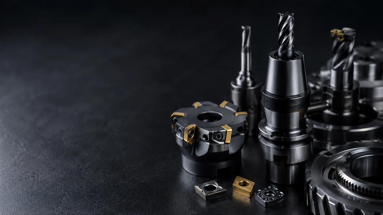
Physical vapor deposition, commonly called PVD coating, is widely used to improve the surface performance of CNC-machined tools and mechanical components. A properly selected PVD coating can reduce abrasive wear, adhesive wear, galling, scuffing, fretting, and surface damage while adding only a thin functional layer to the finished part.
However, “PVD coating” does not describe one material or one fixed level of wear resistance. It describes a family of vacuum-deposition processes capable of producing many different coating systems, including titanium nitride, chromium nitride, titanium carbonitride, titanium aluminum nitride, aluminum chromium nitride, and several carbon-based or diamond-like carbon coatings.
These coatings do not behave identically. A coating that performs well on a hot cutting tool may be unsuitable for a lubricated sliding pin. A low-friction DLC coating that controls galling may fail if the substrate is too soft, the contact load is too high, or the deposition temperature affects the base material. A decorative gold PVD finish may also have a different structure and performance requirement from a qualified wear-resistant TiN coating.
The correct engineering question is therefore not simply, “Is PVD wear-resistant?” It is:
Which PVD coating system, substrate condition, thickness, surface preparation, and inspection method match the actual wear mechanism of this CNC part?
This guide explains how PVD coatings are deposited, when they are suitable for wear-resistant CNC parts, how TiN, CrN, TiAlN, AlCrN, and DLC systems differ, why substrate hardness matters, how coating thickness affects precision features, what commonly causes coating failure, and what should be included on a drawing or purchase specification.
Is PVD Coating the Right Solution for Your Wear Problem?
PVD is a strong candidate when the part has a fundamentally sound design and substrate but requires improved surface behavior. It is less successful when the underlying material, load distribution, lubrication, geometry, or heat treatment is already inadequate.
When PVD Coating Is Usually a Good Candidate
PVD coating should be considered when a CNC part experiences one or more of the following:
- Sliding contact against metal, polymer, or composite surfaces
- Abrasive particles or repeated rubbing
- Galling or cold welding between similar metals
- Fretting caused by small repeated movements
- High contact pressure on a properly supported surface
- Repeated forming, cutting, clamping, or release cycles
- A need for lower friction without a thick dimensional build-up
- A requirement for a hard, chemically stable, or temperature-resistant surface
Typical candidates include punches, dies, forming inserts, cutting-tool components, valve parts, sliding pins, shafts, bushings, mold components, gripper parts, collet elements, pump components, and precision actuator parts.
When PVD Is Not Enough by Itself
A thin hard coating cannot compensate for:
- A soft substrate that plastically deforms under load
- Incorrect bearing area or excessive contact stress
- Misalignment between mating parts
- Large impact loads at sharp edges
- Severe surface defects or deep machining marks
- Inadequate lubrication in a system that depends on lubricant
- An unsuitable base alloy for the operating temperature
- Corrosion conditions beyond the capability of the coating system
If the substrate dents or yields beneath a brittle hard coating, the coating can crack, chip, or delaminate. This is sometimes described as an “eggshell” problem: the hard outer layer is not adequately supported by the softer material below it.
Wear Resistance Must Be Defined by the Contact System
Wear performance depends on the complete tribological system, including:
- Substrate hardness and elastic modulus
- Coating hardness, toughness, and residual stress
- Counterface material and roughness
- Contact pressure
- Sliding speed and distance
- Impact or vibration
- Lubricant and temperature
- Dust, chips, or abrasive contamination
A coating should therefore be selected from test data or supplier experience that resembles the intended application. A general hardness value alone does not predict service life.
| Part condition | Is PVD a strong candidate? | Main engineering concern |
|---|---|---|
| Hardened steel sliding pin with galling | Often yes | Choose a low-friction coating compatible with the load |
| Soft aluminum part under concentrated impact | Usually not without substrate support | The aluminum may deform beneath the coating |
| Injection mold component with abrasive polymer | Often yes | Abrasion, release behavior, and coating temperature |
| Decorative stainless panel | Possible, but wear qualification may be unnecessary | Decorative PVD and tribological PVD are different requirements |
| High-temperature cutting insert | Yes, with a suitable nitride coating | Oxidation resistance and thermal stability |
| Precision shaft with a tight bearing fit | Possibly | Coating thickness and final fit must be controlled |
| Part with heavy rust and pitting | No as a repair method | The substrate must be repaired or replaced first |
| Dry sliding stainless-on-stainless contact | Often | Adhesive wear, galling, and counterface compatibility |
What Is PVD Coating?
Physical vapor deposition is a vacuum-based process in which a solid coating material is converted into vapor, transported through a low-pressure environment, and deposited as a thin film on a component.
PVD is not one single machine cycle. Common industrial methods include arc evaporation, electron-beam evaporation, and several forms of sputtering, including magnetron sputtering and high-power impulse magnetron sputtering.
Coating Material Is Vaporized in a Vacuum Chamber
A metal target or source material is evaporated or sputtered inside a vacuum chamber. The released atoms or ions travel through the chamber toward the parts.
For reactive PVD coatings, gases such as nitrogen, carbon-containing gases, or oxygen may be introduced. These gases react with the vaporized metal to form nitrides, carbonitrides, oxides, or other compound coatings.
For example:
- Titanium and nitrogen can form TiN
- Chromium and nitrogen can form CrN
- Titanium, aluminum, and nitrogen can form TiAlN
- Aluminum, chromium, and nitrogen can form AlCrN
The Coating Builds as a Thin Functional Film
Wear-resistant PVD coatings are normally only a few micrometres thick. An industry overview for precision components describes PVD coating thicknesses of approximately 0.5 to 5 micrometres, although actual systems can fall outside that range.
The thin layer is valuable for precision parts because it can create a much harder or lower-friction surface without adding the thickness associated with thermal spray, hard chrome, paint, or powder coating.
Thin does not mean dimensionless. On a coated external diameter, coating is added to both sides. A 3 μm coating on each surface can increase the measured diameter by approximately 6 μm when coverage is uniform.
PVD Is a Line-of-Sight-Influenced Process
Atoms and ions move from the coating source toward the component. Part rotation and plasma conditions improve coverage, but surfaces that directly face the source generally coat more easily than shielded areas.
Coverage can become less uniform inside:
- Deep blind holes
- Long narrow bores
- Enclosed pockets
- Closely spaced features
- Overlapping assemblies
- Threads with limited exposure
The coating supplier should review geometry and fixturing before promising uniform thickness on all surfaces.
Which Types of Wear Can PVD Coatings Control?
“Wear-resistant” is too broad to serve as a coating specification. Different damage mechanisms require different combinations of hardness, toughness, friction, chemical stability, and adhesion.
Abrasive Wear
Abrasive wear occurs when hard particles or rough surfaces cut, plow, or scratch a component. It is common in cutting tools, forming dies, powder-handling equipment, filled-polymer molds, and components exposed to dust or chips.
Hard nitride coatings such as TiN, TiCN, TiAlN, AlTiN, AlCrN, and CrN can reduce penetration by abrasive particles when the coating is well supported by the substrate.
High hardness alone is not enough. A coating with poor adhesion or excessive brittleness can fracture under repeated abrasive loading.
Adhesive Wear and Galling
Adhesive wear occurs when two contacting surfaces locally bond and tear material away during movement. Severe adhesive wear can produce galling, scuffing, seizure, or material transfer.
It commonly affects:
- Stainless-on-stainless sliding pairs
- Forming tools processing aluminum or galvanized sheet
- Valve and pump parts
- Threaded or clamping components
- Dry-running mechanisms
Low-friction carbon-based coatings and carefully selected nitride systems can reduce adhesion between the mating surfaces. The counterface must also be controlled; a rough uncoated mating part can rapidly damage a coated surface.
Fretting, Rolling Contact, and Impact Fatigue
Fretting develops under small repeated movements and vibration. Rolling contacts and impact-loaded parts introduce cyclic stress at or beneath the surface.
These applications need more than maximum coating hardness. They may require:
- High coating toughness
- Low residual stress
- A graded or multilayer architecture
- A load-bearing interlayer
- A sufficiently hard substrate
- Smooth interfaces and controlled edge geometry
A multilayer DLC system with a CrN support layer, for example, may be selected for high-load sliding or rolling contact because the interlayer supports the low-friction carbon layer. The exact solution remains application-specific.
How Do TiN, CrN, TiAlN, AlCrN, and DLC Differ?
Coating names identify chemistry, but commercial coating systems may also contain adhesion layers, gradient layers, multilayers, nanolayers, or dopants. Two coatings both described as “DLC” or “TiAlN” may therefore have different properties.
TiN and TiCN for General Wear Resistance
Titanium nitride is one of the best-known PVD hard coatings. It is recognized by its gold color and is used on cutting tools, forming tools, medical instruments, food-cutting components, and mechanical parts.
Typical advantages include:
- High hardness
- Good abrasion resistance
- Established industrial processing
- A recognizable wear-indicator color
Titanium carbonitride can offer higher hardness and improved abrasive-wear behavior in selected applications, but its friction, toughness, and temperature capability must be matched to the operating condition.
CrN for Toughness, Corrosion Support, and Forming Applications
Chromium nitride is commonly selected when a balance of hardness, toughness, wear resistance, and chemical stability is needed. It is used on forming tools, molds, cutting blades, pump parts, and mechanical components.
CrN can be useful where impact fatigue or coating toughness matters more than achieving the highest possible hardness. It is also frequently used as a support or adhesion layer below carbon-based coatings.
Whether CrN improves corrosion performance depends on coating density, defects, substrate preparation, edge coverage, thickness, and service environment. A thin PVD film should not be assumed to be a completely pore-free corrosion barrier.
TiAlN and AlCrN for Elevated-Temperature Wear
Titanium aluminum nitride, aluminum titanium nitride, and aluminum chromium nitride are widely used for cutting tools and other high-temperature wear applications.
These coating families are selected for combinations of:
- High hardness
- Hot hardness
- Oxidation resistance
- Abrasive-wear resistance
- Thermal protection of the substrate
They are not automatically the best choice for low-temperature sliding components. A coating optimized for hot cutting may have a higher friction coefficient or different toughness than a coating designed for lubricated mechanical movement.
DLC and Carbon-Based Coatings for Low Friction
Diamond-like carbon is a broad family of amorphous carbon coatings. Different DLC structures can be deposited by PVD, PACVD, or combined processes.
DLC systems are often selected for:
- Low friction
- Resistance to adhesive wear
- Protection against galling and scuffing
- Dry or minimally lubricated movement
- Precision components under repeated sliding
DLC temperature capability and compatibility vary considerably. Hydrogenated DLC, metal-doped DLC, and hydrogen-free ta-C should not be treated as identical products.
| Coating family | Typical strengths | Common limitations | Example applications |
|---|---|---|---|
| TiN | General abrasion resistance, established process, gold color | Not the best option for every high-temperature or low-friction contact | Cutting tools, punches, blades, instrument parts |
| TiCN | High hardness and abrasive-wear resistance | Toughness and friction must be reviewed | Forming tools, cutting tools, wear components |
| CrN | Toughness, wear resistance, chemical stability | Performance depends strongly on contact system and coating structure | Molds, forming tools, pump and valve parts |
| TiAlN / AlTiN | Hot hardness and oxidation resistance | May not be optimal for low-temperature sliding | Drills, mills, inserts, hot-wear tools |
| AlCrN | High-temperature wear and oxidation resistance | Requires suitable substrate and process temperature | Cutting and forming tools |
| DLC / a-C:H / ta-C | Low friction, adhesive-wear and galling resistance | Temperature and impact capability vary by DLC type | Shafts, pins, valve parts, automotive and precision components |
| Multilayer or gradient coating | Can combine adhesion, support, toughness, and low friction | Performance cannot be judged from top-layer name alone | Highly loaded sliding and rolling components |
Why Does the CNC Part Material Matter?
PVD performance is determined by the coating-substrate system, not the coating alone. The substrate must support the film mechanically and tolerate the deposition process.
Hardened Tool Steels and Stainless Steels
Hardened tool steels are common PVD substrates because they provide strong load support. Examples include:
- D2 and similar cold-work tool steels
- H13 and hot-work tool steels
- M2 and other high-speed steels
- Hardened stainless steels such as 420 or 440C
- Precipitation-hardening stainless steels such as 17-4 PH
The tempering temperature and heat-treatment condition must be compatible with the coating temperature. If the deposition cycle exceeds a critical tempering range, substrate hardness, dimensions, or mechanical properties may change.
Carbide and Other Hard Substrates
Cemented carbide is widely coated for cutting and forming applications. Substrate composition, cobalt content, surface roughness, edge preparation, and cleaning influence adhesion and fatigue performance.
A very sharp cutting edge may be intentionally honed before coating to reduce edge chipping. The correct edge preparation depends on tool geometry, workpiece material, coating thickness, and cutting conditions.
Aluminum, Copper, and Soft Alloys
Some PVD processes can coat aluminum, copper, and other lower-melting or softer alloys, especially when low-temperature coating systems are available. Nevertheless, these substrates create additional risks:
- Insufficient load support
- Thermal distortion
- Loss of heat-treatment condition
- High thermal expansion mismatch
- Surface oxide or adhesion difficulties
A hard film on a soft aluminum substrate may resist light scratching but fail under high point loads because the base metal yields. A duplex process, hard anodized interlayer, electroless nickel layer, or different substrate may be needed, but compatibility must be qualified.
| Substrate | General PVD suitability | Key review points |
|---|---|---|
| Hardened tool steel | Very common | Tempering temperature, hardness, edge condition |
| Hardened stainless steel | Common | Heat treatment, corrosion requirements, surface preparation |
| Austenitic stainless steel | Common for components | Load support, galling mechanism, nitrided or hardened support if needed |
| Cemented carbide | Very common for tools | Binder content, roughness, edge preparation, adhesion |
| Titanium alloy | Application-dependent | Adhesion, friction, substrate temperature, fatigue |
| Aluminum alloy | Possible with limitations | Soft-substrate support and thermal sensitivity |
| Copper alloy | Possible with specialized processes | Softness, oxidation, adhesion, thermal expansion |
| Plastic | Usually decorative or specialized | Vacuum compatibility, temperature, conductivity, pretreatment |
How Do Surface Finish and Part Geometry Affect PVD Adhesion?
PVD follows the existing surface rather than filling deep defects. The incoming CNC finish therefore influences adhesion, roughness, friction, appearance, and fatigue life.
Cleanliness Is Critical Before Coating
Oil, coolant, polishing compound, rust, oxide, fingerprints, silicone, and cleaning residue can interfere with adhesion.
A typical preparation route may include:
- Degreasing
- Ultrasonic cleaning
- Rinsing and drying
- Vacuum heating or outgassing
- Plasma or ion cleaning
- Etching immediately before deposition
Parts with blind holes or porous surfaces can release trapped contamination inside the vacuum chamber. The coating supplier may reject components containing oil-filled pores, incompatible brazing material, adhesives, or assembled seals.
Roughness Can Improve Mechanical Contact but Harm Performance
A controlled surface texture may support adhesion, but excessive roughness creates high local stress, thin coverage on peaks, and poor sliding behavior.
PVD usually reproduces the substrate texture. A rough machined surface remains rough after coating and may become more abrasive against the mating part.
Critical sliding surfaces may require grinding, lapping, polishing, or superfinishing before PVD. Post-coating polishing is also possible for some systems, but it must not remove or damage the thin film.
Sharp Edges and Recessed Features Need Review
Sharp edges may receive concentrated coating flux and develop high stress. They are also vulnerable to impact and chipping.
Designers should evaluate:
- Controlled edge radii
- Removal of fragile burrs
- Access for cleaning and coating
- Orientation during rotation
- Shielding by adjacent features
- Rack and contact locations
Deep recessed areas may receive thinner or compositionally different coatings. If an internal bore is the actual wear surface, it must be identified before quoting.
How Does PVD Coating Affect Dimensions, Fits, and Threads?
PVD coatings are thin, but precision components can have tolerances comparable to the coating thickness. Final dimensions must be planned rather than assumed.
Coating Adds Material to Every Exposed Surface
For a nominal coating thickness of 3 μm:
- An exposed flat surface rises by approximately 3 μm
- An external diameter can increase by approximately 6 μm
- An internal diameter can decrease by approximately 6 μm
- A slot can narrow by approximately 6 μm when both walls are coated
These are simplified geometric calculations. Actual thickness can vary with orientation, edge effects, source position, coating method, and feature accessibility.
Threads and Precision Fits May Need Masking
PVD can alter thread pitch diameter and crest geometry. A thick or rough coating can cause:
- Thread binding
- Excessive installation torque
- Loss of gauge acceptance
- Damage to the coating during assembly
- Debris generation
Depending on the design, threads may be masked, machined with allowance, coated and functionally gauged, or added as inserts after coating.
Press fits, bearing seats, seal lands, and gauge surfaces require the same review.
Final Inspection Should Usually Occur After Coating
When a feature is coated and functionally critical, the drawing should state that its dimension applies after PVD.
The supplier must account for:
- Machining tolerance
- Coating-thickness target
- Thickness variation
- Measurement method
- Possible post-coating polishing
A broad instruction such as “PVD all over” is insufficient for a close-tolerance assembly.
What Happens During the PVD Coating Process?
A wear-resistant PVD process usually includes several preparation and deposition stages. The exact cycle depends on coating chemistry and equipment.
Step 1: Review and Preclean the Part
The coating supplier reviews:
- Base material
- Heat-treatment condition
- Previous surface treatments
- Dimensions and tolerances
- Surface roughness
- Masking areas
- Rack-contact areas
- Operating wear mechanism
The part is then cleaned to remove coolant, oil, polishing compound, oxides, and handling contamination.
Step 2: Load, Evacuate, Heat, and Plasma-Clean
Parts are mounted on fixtures and placed in the vacuum chamber. The chamber is evacuated, and the parts may be heated to remove moisture and volatile contamination.
Ion or plasma cleaning activates the surface immediately before coating. This stage is important because contamination remaining at the interface can reduce adhesion.
Deposition temperature must remain compatible with the substrate, heat treatment, brazed joints, and dimensional stability.
Step 3: Deposit the Adhesion and Functional Layers
The process may begin with a thin metallic adhesion layer or graded transition layer. The functional coating is then deposited by evaporation or sputtering with controlled reactive gas.
Parts are often rotated to improve uniformity. Multilayer systems may alternate chemistry or composition to control residual stress, crack propagation, toughness, and friction.
Step 4: Cool, Unload, and Inspect
After deposition, the chamber and components are cooled under controlled conditions. Parts are unloaded and inspected for:
- Color and appearance
- Coating coverage
- Thickness
- Adhesion
- Surface defects
- Critical dimensions
- Required mechanical or tribological performance
Masking and rack-contact areas may remain uncoated. Their permitted location should be agreed before production.
What Causes PVD Coating Failure?
A failed PVD coating should be analyzed by failure mode. “The coating wore off” does not identify whether the cause was normal wear, adhesion loss, substrate deformation, impact cracking, corrosion undercutting, or incorrect coating selection.
Delamination and Poor Adhesion
Possible causes include:
- Oil or oxide at the interface
- Inadequate plasma cleaning
- Excessive substrate roughness
- Incorrect adhesion layer
- High residual coating stress
- Thermal-expansion mismatch
- An incompatible previous coating
Adhesion can also appear adequate in a simple test but fail under cyclic contact if the substrate and interlayer do not support the real load.
Cracking and Chipping
Cracking may result from:
- Substrate deformation
- Heavy impact
- Sharp-edge stress concentration
- Excessive coating thickness
- High residual stress
- Fatigue under rolling contact
Increasing coating hardness or thickness does not automatically solve chipping. A tougher coating, multilayer system, harder substrate, larger edge radius, or lower contact stress may be required.
Premature Wear Without Delamination
A coating can remain attached yet wear too quickly because:
- The coating chemistry does not match the wear mechanism
- The counterface is too rough
- Abrasive contamination enters the contact
- The service temperature exceeds coating capability
- Lubrication is missing or incompatible
- Coating thickness is insufficient for the duty cycle
This is a selection or system-design problem, not necessarily a deposition defect.
| Observed failure | Possible cause | Corrective direction |
|---|---|---|
| Large flakes detach | Interface contamination or poor adhesion | Review cleaning, plasma etching, interlayer, and substrate |
| Edge chipping | Sharp geometry, impact, or high local stress | Add edge preparation or choose a tougher system |
| Network of cracks | Substrate deformation or excessive residual stress | Improve support and revise coating architecture |
| Polished wear track without flaking | Normal wear or insufficient thickness | Compare service life with acceptance target |
| Rapid galling | Wrong coating/counterface combination | Select a lower-adhesion, lower-friction system |
| Rust appears through coating | Pores, defects, exposed edges, or unsuitable substrate | Do not assume thin PVD is a complete corrosion barrier |
| Fit becomes too tight | Coating thickness omitted from tolerance stack | Apply allowance, masking, or final coated inspection |
| Uneven color or thickness | Geometry, shielding, fixturing, or current/flux distribution | Revise loading orientation and coverage requirement |
How Should Wear-Resistant PVD Coatings Be Tested?
No single test proves that a coating will perform in every machine. Inspection should combine coating characterization with tests relevant to the actual contact condition.
Thickness, Hardness, and Roughness
Common characterization methods include:
- Calotest or crater-grinding thickness measurement
- Cross-sectional microscopy
- X-ray fluorescence for suitable coating systems
- Instrumented indentation for hardness and elastic modulus
- Profilometry for surface roughness
- Optical or electron microscopy for defects
Fraunhofer coating laboratories identify hardness, modulus, adhesion, friction, wear, thickness, residual stress, roughness, composition, and microstructure as relevant coating-characterization properties.
Scratch and Indentation Adhesion Tests
ISO 20502 describes scratch testing of ceramic coatings using a diamond stylus with constant or increasing normal force. It is intended to promote and evaluate adhesive or cohesive failure and is suitable for coatings up to 20 μm thick.
ASTM C1624-22 covers quantitative single-point scratch testing for hard ceramic coatings, including carbides, nitrides, oxides, diamond, and diamond-like carbon on metal and ceramic substrates.
ISO 26443:2023 provides a Rockwell indentation method for qualitative evaluation of ceramic-coating adhesion up to 20 μm thick.
Critical load results should not be compared blindly between laboratories unless stylus geometry, loading rate, substrate, coating thickness, surface finish, and failure definition are equivalent.
Wear Tests and Functional Validation
Possible wear tests include:
- Pin-on-disk testing
- Ball-on-disk testing
- Reciprocating sliding tests
- Micro-abrasion testing
- Fretting tests
- Rolling-contact fatigue tests
- Application-specific cycle testing
ISO 26424 describes a micro-scale abrasion method for measuring the abrasive wear rate of ceramic coatings.
For a production component, the most useful validation may be an assembly-level test using the real counterface, lubricant, pressure, temperature, contamination, and motion cycle.
How Should PVD Coating Be Specified on a CNC Drawing?
A note that says only “PVD coat” does not identify chemistry, thickness, hardness, color, friction, adhesion, temperature capability, or wear mechanism.
Define the Coating System and Functional Requirement
The drawing or purchase specification should identify:
- Coating family or qualified commercial coating
- Required thickness and tolerance
- Required color only when appearance matters
- Maximum deposition temperature when substrate properties are sensitive
- Target wear, friction, or temperature function
- Applicable industry or customer specification
When a proprietary commercial coating has been validated, it may be safer to specify the approved coating system and supplier rather than converting it into a simplified chemistry name.
Identify Coated, Masked, and Rack-Contact Areas
The drawing should clearly show:
- Functional wear surfaces
- Threads to be masked
- Bearing and press-fit seats
- Grounding or electrical contact areas
- Sealing faces
- Permitted fixture-contact points
- Surfaces where color variation is acceptable
“Coat all surfaces” may be impossible when the part requires electrical contact to the fixture or contains shielded internal features.
State Final Dimensions and Inspection Requirements
Critical dimensions should be defined after coating when those surfaces receive PVD.
The specification may also require:
- Coating-thickness report
- Scratch or indentation adhesion test
- Hardness report
- Surface-roughness measurement
- Visual acceptance criteria
- Functional wear test
- Certificate of conformance
- Process-lot traceability
Example drawing note: Apply wear-resistant PVD coating [approved coating designation] to identified surfaces after final heat treatment and finish grinding. Coating thickness: [specified range]. Final dimensions apply after coating. Mask identified threads, bearing seats, and electrical contact areas. Deposition temperature shall not exceed the approved limit for the substrate condition. Verify coating thickness and adhesion using the specified methods and provide a certificate of conformance.
The bracketed information must be replaced with actual project requirements.
Which CNC Parts Commonly Use Wear-Resistant PVD Coatings?
PVD is used across tooling and component applications, but the coating requirements differ between a cutting edge and a sliding mechanical part.
Cutting, Forming, and Mold Components
Examples include:
- Milling cutters and drills
- Cutting inserts
- Punches and dies
- Forming tools
- Injection-mold cores and inserts
- Ejector pins
- Food-cutting blades
These applications may prioritize abrasion resistance, hot hardness, oxidation resistance, release behavior, or reduced material adhesion.
Automotive, Aerospace, and Motion Components
Examples include:
- Fuel-system components
- Valve-train parts
- Rotor and actuator shafts
- Sliding pins
- Precision gears and contact elements
- Aerospace actuator components
- Clamping and collet components
Low friction, fatigue resistance, contact pressure, lubricant compatibility, and coating temperature are often more important than color.
Medical, Food, Optical, and Automation Parts
Potential applications include:
- Surgical cutting tools
- Medical instrument components
- Food-processing blades and forming parts
- Robot gripper components
- Pick-and-place mechanisms
- Optical positioning hardware
- Precision laboratory mechanisms
These projects may also require biocompatibility, food-contact suitability, cleanability, sterilization compatibility, low particle generation, or controlled appearance. A generic PVD coating claim does not prove compliance with these requirements.
How Does RapidMFGPro Support PVD-Coated CNC Part Projects?
PVD performance depends on coordination among CNC machining, heat treatment, polishing, coating, and final inspection. Treating the coating as an isolated purchase after the part is completed increases the risk of poor adhesion, altered fits, substrate softening, and unsuitable coating selection.
RapidMFGPro operates as a manufacturing resource and supplier-matching platform. It helps connect projects with machining and coating resources suited to the part’s material, geometry, wear mechanism, tolerance, and documentation needs.
Reviewing the Wear Mechanism and Base Material
A project review can identify:
- Whether wear is abrasive, adhesive, fretting, rolling, or impact-related
- Whether the substrate is hard enough to support a thin film
- Whether heat treatment must occur before coating
- Whether deposition temperature may affect the alloy
- Whether DLC, nitride, or another coating family is appropriate
- Whether a coating is likely to outperform material change or lubrication
This prevents coating selection from being based only on color, maximum hardness, or a generic PVD label.
Matching Machining, Heat Treatment, and Coating Capabilities
The manufacturing route may need:
- Precision CNC machining
- Vacuum heat treatment
- Nitriding or another duplex treatment
- Grinding, lapping, or polishing
- Low-temperature PVD
- Custom masking and fixturing
- Thickness and adhesion testing
- Post-coating dimensional inspection
The objective is to match the complete process chain rather than locate any supplier that owns a PVD chamber.
Validating Samples Before Production
Initial samples or a low-volume batch can be used to verify:
- Coating thickness and uniformity
- Final fit and thread function
- Adhesion and edge behavior
- Surface roughness
- Wear against the actual mating material
- Appearance and rack marks
- Process documentation
Once the substrate condition, coating system, deposition route, and inspection plan are validated, the approved process can be carried into production.
Frequently Asked Questions About PVD Coating
Is PVD Coating Always Wear-Resistant?
No. PVD is a deposition method, not a single coating. Wear resistance depends on coating chemistry, structure, thickness, adhesion, substrate support, counterface, load, temperature, and lubrication.
How Thick Is a Wear-Resistant PVD Coating?
Many precision component coatings are only a few micrometres thick, often within an approximate 0.5–5 μm range. The correct thickness depends on the coating system, geometry, application, and dimensional tolerance.
Does PVD Make a CNC Part Harder?
PVD can create a much harder surface film, but it does not harden the complete component core. The substrate retains its original bulk properties unless a separate heat treatment or diffusion process is used.
Can PVD Coating Chip or Peel?
Yes. Poor cleaning, inadequate adhesion, high residual stress, impact, sharp edges, or substrate deformation can cause cracking, chipping, or delamination.
Can Aluminum CNC Parts Receive PVD Coating?
Some aluminum alloys can be PVD coated using suitable low-temperature processes and pretreatments. However, soft-substrate deformation, thermal sensitivity, and adhesion must be reviewed before using PVD for high-load wear resistance.
Is DLC a PVD Coating?
Some DLC coatings are deposited by PVD, while others use PACVD or combined PVD/PACVD methods. “DLC” describes a carbon-based coating family rather than one deposition process or one fixed property set.
Does PVD Coating Improve Corrosion Resistance?
Some PVD systems can improve corrosion behavior, but thin films may contain defects or leave edges and masked surfaces exposed. PVD should not automatically be treated as a completely sealed corrosion barrier.
Can Threads Be PVD Coated?
Yes, but coating thickness affects pitch diameter and assembly torque. Critical threads may require masking, allowance, functional gauging, or a validated thin coating.
Conclusion
PVD coating can significantly improve the wear performance of CNC parts when the coating system matches the actual contact mechanism and is supported by a suitable substrate. TiN, CrN, TiAlN, AlCrN, and DLC coatings offer different combinations of hardness, toughness, friction, and temperature resistance.
PVD should not be used to compensate for poor machining, excessive load, soft substrates, or incorrect material selection. Surface preparation, deposition temperature, thickness, geometry, adhesion, final dimensions, and application-level testing must be planned together.
RapidMFGPro helps review these requirements and match CNC projects with suitable machining, heat-treatment, PVD coating, and inspection resources.
Reference Sources
- ISO 20502:2005 — Determination of Adhesion of Ceramic Coatings by Scratch Testing
- ISO 26443:2023 — Rockwell Indentation Test for Evaluation of Adhesion of Ceramic Coatings
- ISO 26424:2008 — Determination of the Abrasion Resistance of Coatings by a Micro-Scale Abrasion Test
- ASTM C1624-22 — Adhesion Strength and Mechanical Failure Modes of Ceramic Coatings by Scratch Testing
- Fraunhofer IST — Friction Reduction and Wear Protection
- Fraunhofer IWS — PVD and DLC Coating Characterization
- Oerlikon Balzers — PVD Coatings for Precision Components
- Oerlikon Balzers — DLC and Carbon-Based Coatings
Need Help Reviewing a Custom Part?
Share your CAD file and requirements to request supplier matching. Supplier capability and commercial terms must be verified before order placement.
Request Supplier Match